2003 Chevrolet Trailblazer Stoplight Inop

This 2003 Chevrolet Trailblazer came in with the complaint that the right stoplight does not work with the tail / park lights on. After removing the assembly by opening the rear hatch, removing the two retaining screws and sliding the assembly out of the vehicle, I had to work very hard to unplug the harness connector and this is what I found.

Rust and rotted terminals.

I spliced in a new harness connector. To order a new connector please click here.

Installed it into a new circuit board and reassembled the light. To order a new circuit board please click here.

2003 GMC Envoy, Low Beam Headlight Inop

This 2003 GMC Envoy came in with the complaint that the passenger side low beam would not work. The customer further stated that they had tried to replace a burnt socket. Well let’s pull the light assembly out and see what kind of mess we have. There are two retainers that have to be lifted up to remove the light assembly.

DSC02452

Once the retainers are pulled up the headlight assembly can be wiggled out far enough to unhook the harness connectors.

Depress the locking tab and rotate the light socket to remove.

With the assembly removed the rubber sealing cover can be removed.

DSC02448

This does not look very good. The customer tried to install a sealed type connector for a 9006 bulb but it will not fit without removing a lot of material. Twisting the wires together and wrapping with tape is not a good long lasting way of repairing either. If you need to see and have nothing else to work with it will do though.

<

The customer still had the original burnt connector. Pretty bad.

I cut the wires back in order to stagger the joints. I then installed quality splice connectors and heat shrink tubing.

Next, I installed the connector onto the new bulb and installed the bulb into the lamp assembly and reinstalled into vehicle. A new bulb must be installed when the connector is replaced or the repair will not last very long. To purchase the low-beam connector, please click here. If you need to purchase the high-beam connector, please click here.

Removing The Tilt Lever Handle On GM Cars & Trucks

It is kind of funny to me but this is one of those things I tend to take for granted that the average person working on his or her car has difficulty with. I think for me it must be a combination of experience and hand strength that makes it so easy to remove the tilt handles on GM cars and trucks that look like the following picture.

I firmly grasp the handle and pull it straight out to release the internal retention clips. Much like you would pull a socket off of a ratchet.

Once I feel the handle release it is very easy to just continue pulling,

Until it is fully removed.

The following is a close up picture of the internal retaining clip.

You may want to use a screw driver or pry bar to assist in removing the handle. Just be careful not to scar the plastic. Hope this helps. Please let me know if I overlook anything else that I may be taking for granted that needs more explaining.

2004 Chevrolet Tahoe Blows Hot Air

This 2004 Chevrolet Tahoe came in with the complaint that the air on the driver’s side would change from cold to hot while driving down the road. When it shifted to hot the customer could not get it to turn back cold. Sounds like a faulty air mix actuator to me. I checked codes and sure enough there was a code B0408 for the left air temperature actuator. I checked the commanded position versus the actual position and there was a large difference in the counts. This is only important if you have a scan tool that will access this system. There are other tricks that can be used to test that I will show later. The driver’s or left air mix actuator is located on the lower passenger side of the dash. If present the hush panel has to be removed. This one is easy because there is no floor mounted center console. If you have a floor console please see the information at this link to see how to deal with one screw.

I removed the four 7 mm headed screws and pulled the panel out of the way.

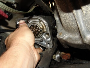
I knew I was changing the actuator, so I disconnected the wiring harness connector and removed the two 5.5 mm headed screws

Then the actuator simply pulls down. There may be some resistance if the actuator is at the full stop position.

Slide the new actuator into position, install the mounting screws and reconnect the wires. After this was done I recalibrated the actuator with my Tech 2 scan tool. If you do not have a scan tool you may disconnect the battery for one minute. Reconnect the battery and start the engine. The key point is DO NOT TOUCH the a/c controls for at least one full minute. Actually, I prefer to wait 4 minutes because I remember reading that a few years ago and the extra time does not hurt anything. After one full minute turn the ignition off. Restart the engine and check the door operation.

Proper operation can be seen in the data stream in that the commanded and actual positions are at nearly identical counts.

To do testing with a voltmeter at the harness connector you will need to test the following. Check for ignition power on the brown wire. If power is not present check the HVAC 1 fuse in the left interior fuse box. Check for a 5 volt reference signal on the light blue/black wire. All of the next tests must be done with the harness connector plugged into the actuator. The yellow wire is a low reference wire from the control head (ground, internal system not chassis). The light blue wire is the position signal wire from the actuator to the control head. If the actuator will move the voltage will change up or down depending on the movement of the actuator (between 0 and 5 volts). The dark blue wire will have basically three different voltages that are important. 5 volts is a signal to increase the door position, 0 volts is a signal to decrease the door position and 2.5 volts is a signal to hold the door position. So with that information turn the ignition on and touch the black lead of your voltmeter to the yellow wire. Touch the red lead of your meter to the brown wire and check for a reading of battery voltage. Next touch the red lead to the dark blue wire and check for either 0, 2.5 or 5 volts depending on command. You will probably need an assistant to adjust the temperature control for the driver’s side.

Something else you need to know. If you buy a new actuator make sure the part numbers match. At the time of this writing the aftermarket (non dealer) application books are incorrect. You have to buy an actuator for the passenger side to get the correct actuator for the driver’s side. Crazy but true. I cannot think of the number of actuators I have changed that have already been replaced by others. If you install the wrong actuator, it will rotate to a full stop and never move again.

This is the box that the actuator I installed came in and the numbers on the actual parts matched (52402588). The short number is 15-72971. Long number 89018365 and it is listed as the passenger or top air mix actuator. To order this part please click here.

How To Check Terminal Spring Tension

I have recommended this test many times and finally have had enough time to do a quick post about it. The terminal to be tested is a female 280 metri-pack terminal. To test the spring tension of a female terminal you need a male terminal. Most people do not have factory terminals just laying around so this is what I recommend.

Locate any standard mini fuse as shown in the following picture.

Bend one of the blades over or you could cut one off.

Slide the straight fuse blade into the terminal to be tested.

The test comes in checking the amount of force needed to remove the fuse from the female terminal. This is called a drag test. It takes a little while to develop a feel for what is good and what is not but you can easily test several and compare the results or feel.

I made up fused jumper wires a long time ago to do the same thing. In the next picture you can see that the fuse blade terminal and a factory 280 metri-pack terminal are the same size.

2000 GMC Yukon, Rear Lights Inop

This 2000 GMC Yukon came in with the complaint that at different times the stop lights, tail lights, turn signals and back up lights stop working. I did the basis bulb and socket tests and found nothing wrong. When I got to looking a little deeper in the system I found this rear harness junction block at right rear inner fender panel. I disconnected the harness connectors and water came out. Many of the terminals were green and this was the source of the lighting complaint. I carefully cleaned and tightened each of the terminals in the harness connectors and installed a new junction block. I also inspected and found that there had been accident damage at this point in the past. I had to beat the mounting panel back flat. I am reasonably sure that the junction had been cracked.

I informed the customer that if any of the problems returned we may have to start replacing harnesses. So far it has been 3 months and no problems as of yet.

I think that this is going to be a greater source of mysterious rear lighting problems on Chevrolet and GMC light trucks ( Silverado, Suburban, Tahoe, Sierra, Yukon, Escalade and Avalanche )from 1999 through at least 2007 Classic series. Maybe even newer models.

Need to buy a new rear junction block.? I prefer using OEM quality parts. Please click on the affiliate image link above to purchase. 

Want a less expensive alternative? Then click on my affiliate image link below to purchase.

1999 Mercury Sable, P0401 Insufficient EGR Flow

This 1999 Mercury Sable came in with the check engine light on and a code P0401 for insufficient EGR flow. Luckily the EGR valve and the DPFE sensor are easily accessible on this car.

I set may scan tool up to view DPFE voltage and connected my hand vacuum pump to the EGR valve. This can also be done with a voltmeter connected to the DPFE signal wire.

The voltage with the key on and the engine off was .44 volts. The voltage with the key on and the engine running was the same voltage. The voltage with the key on, the engine running and the EGR valve opened with the vacuum pump was also .44 volts. The engine also started running poorly and almost stalled, this indicated that the EGR valve and passages are open, good. Looks like probably the DPFE sensor is faulty.

I turned the engine off and switched the key back on, jumped the 5 volt reference wire to the DPFE signal wire and monitored voltage. The voltage went close to 5 volts. Diagnosis and replacement of a faulty DPFE sensor.

The original DPFE sensor is on the right and was of a metallic design the replacement has been improved and now is made of plastic. The metal one tended to corrode badly.

1992 Buick Park Avenue, Blower Inop

This 1992 Buick Park Avenue came in with the complaint that the blower did not work. Customer also stated that the blower motor had been replaced about a year ago. The blower motor is located in the center of the firewall under the hood.

The first thing that I found was that the blower motor harness connector and the terminals in the blower motor were heat damaged, burnt. I had also noticed that the harness connector showed significantly more damage that the blower motor terminals. Diagnosis of faulty connector and motor assembly.

I replaced the motor by removing the mounting screws and pulling the motor assembly from the HVAC box.

Next, I spliced in a new harness connector assembly. To order a new repair harness please click here.

Installed the new blower motor with the oxygen sensor wire caught under the motor. Of course I removed the motor and put the wire back where it was supposed to be.

As shown in the following picture and connected the new harness to the motor. I cannot stress this next point enough. The only reason the blower motor that was installed only a year ago failed was because the installer failed to replace the connector at the same time. ANY time a burnt harness connector is found it and the component it attaches to must be replaced at the same time or early failure will occur!!!!!!

1994 Lexus GS300, Starter Clicks

This 1994 Lexus GS300 came in with the typical “starter clicks but won’t crank” condition. After a quick check to make sure that battery and cables were okay, I started to remove the starter. The starter can be seen at the rear of the driver’s side of the engine but it has to be accessed from the bottom.

The next step was to disconnect the wiring from the starter.

DSC01796

Next using long extensions and swivel sockets I removed the bolts that hold the starter to the transmission.

Well with the two attaching bolts removed, I had the starter loose but now I had to figure out how to get it out of the vehicle.

Although I really do not like moving fluid lines if I can find a different way, there seemed no other practical way to extricate the starter from it’s cage.

With the fuel lines disconnected it was reasonably easy to finish removing the starter from the car. To see the procedure for repairing the starter please click here. It  is  very detailed and takes a little while to load.

2003 Toyota 4Runner, A/C Stops Cooling

This 2003 Toyota 4Runner came in with the complaint that the a/c stops cooling after a while and the a/c lights on the dash start flashing. This is a common problem on later model Toyota’s in general. Most of the time it is just a failed compressor clutch relay but sometimes as in this case there is an updated part to correct the condition according to Toyota.

The MG CLT relay (magnetic clutch) is the white one in the center of the following picture.

The new relay I installed is black in color and it is and aftermarket design. I have used quite a few of these and have had no problems as of this post. There is a big difference in the cost of the original Toyota part and the aftermarket version.

The fuse box cover is marked MG CLT for the magnetic clutch relay. A quick test drive to confirm the problem was resolved and this one was done.