1992 Dodge Van, Replacing a Blown Fusible Link

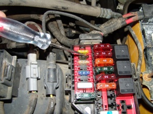
While working on this 1992 Dodge Full Sized Van I located a blown fusible link at the firewall under the hood. I had already started replacing it when I realized that I should post it. I had already selected the proper sized fusible link wire and had spliced it into the wire that it supplied power to. It is fairly cut and dry so I don’t think it should matter too much that I don’t have pictures of it. I did extend the factory wire by about eight inches in case the fusible link ever blew again it would not be as difficult to replace.

In the following picture you can see that the fusible link is connected to two appropriately sized wire extensions and that one end is already installed to the circuit.

Because Chrysler products for many years used this type of gang connection for the fusible links to the main battery lead I have had to develop this technique for splicing back into the battery cable lead. The temptation would be to simply extend the fusible link wiring with the proper sized standard wire and connect it directly to the positive battery cable with an “eye” or “ring” type connector. Unfortunately I found out early on that this will cause problems with the amp gauge operation . Using a pocket knife I remove about on inch of insulation from the main battery cable.

Once the insulation is removed I insert a small screw driver in between the cable wires and separate the wires into two halves making a slot in the cable.

Next I take the new wire to be spliced in, strip off a few inches of insulation and insert the wire through the slot that I created in the cable. I slide it all of the way in until the insulation stops it from going any further. I wind the excess wire around the main cable.

After it is wound tightly around the main cable I hold the windings in place and pull back firmly on the new wire lead. This draws the assembly into a tight mechanical connection.

Once it is pulled into a tight connection I heat the assembly up with a large soldering gun and continue to hold the heat to it until the solder starts to flow. I will some times use a small torch but is easy to make a mess that way.

The soldering gun below shows the large tip installed and the standard tip below. I like the versatility of this solder gun and have been using this type for about twenty years. Not only does it have the two different tips available but I really like that it only takes about 10 – 20 seconds to be hot enough for normal soldering.

Once the connection is sealed I allow it to cool before sealing with live rubber tape.

I then further wrap the connection with standard electrical tape for abrasion resistance.

After it is all sealed back up, I form the wires back into  position with the rest of the harness and tuck it back into the holding straps.

1992 Toyota Tercel, A/C Inop

This 1992 Toyota Tercel came in with the complaint that the a/c compressor would not engage. The customer stated that he had just replaced the compressor (used) and the system was gassed up. I noticed that the indicator light would also no come on when the a/c button was pushed. I looked at the wiring diagram and decided to start with the basics and check the fuse. The fuse for the a/c clutch is not in the main fuse boxes. Instead it is in a small fuse relay box behind the right side of the glove box. To remove the glove box I had to remove one phillips headed screw at the top center of the glove box trim area.

I next had to remove the four 10 mm headed bolts at the four corners of the assembly.

With the glove box out of the way the fuses were easy to see. The top pink PAL fuse is for the blower motor and the red 10 amp fuse is for the a/c clutch.

I thought I would take another picture of some a/c stuff behind the glove box. The harness connector at slightly left of center is the blower resistor. The connector near the bottom and slightly right is the a/c amplifier module.

The system actually went to work with no problem. I checked the wiring at the compressor and informed the customer that the fuse may have blown due to the original compressor locking up or it may be due to wiring. He said he wanted to run it to see how long it would last. Okay!!!

1997 Ford Mustang, No Crank Condition

This 1997 Ford Mustang came in on a hook with a no crank condition, the starter would not work. I turned the key on and checked to make sure the dash lights came on. They did but as soon as I tried to crank the engine they went out. Seems like a battery cable connection. I opened the hood and this is what I found. I have mixed feelings about these painted temporary battery terminal ends. I hate them because they cause so much trouble. I love them because they cause so much trouble and I make my living fixing electrical troubles.

I thought I would show a trick of the trade for checking to see if a battery terminal is actually making contact with the battery post on a top post battery. Using a jumper cable clamp with a lot of tension hook one jaw on a clean metal piece of the terminal and hook the other jaw onto the top of the battery post and make sure it digs in real good. If the vehicle now has enough power to start the terminal, the post or both are corroded or oxidized enough to prevent power from flowing. Keep in  mind that this can be dangerous. A poor connection can create an arc, a battery produces hydrogen gas and together they cause an explosion that can spray battery acid. 
A safer way is to use a voltmeter and do a voltage drop test. Starting at the battery posts and working out to see if the voltage changes.

The positive cable connection was the problem. I think you can see the oxidation in the following picture. The battery post and the terminal were both heavily oxidized

You can also see corrosion under the clamp.

I cleaned the cable back to clean copper and stripped off some insulation, about 3/4″.

I placed a ring terminal over the exposed copper wire and crimped it in place.

I repeated this with the ground cable and soldered both assemblies. Notice I removed the battery. Open flames and hydrogen gas are not a good combination.

I used a butane torch to heat the connection up enough to solder it together.

Then I installed some heat shrink tubing.

I used a heat gun to shrink the tubing and seal the connection.

Repeated on the negative cable assembly.

Installed the ring or eye terminals onto quality marine type battery terminals.

I also installed a protective boot onto the positive cable assembly.

2003 Chevrolet Silverado, Blower

I have been asked many times about the auto blower control on 2003- 2007 Chevrolet Silverado Classic and GMC Sierra Classic trucks so I decided to take some readings on my truck. This also applies to the Tahoe, Yukon, Avalanche, Escalade and Suburbans of the same era with auto a/c controls. The blower control processor is located under the passenger side of the dash.

There are a couple of 7 mm headed screws that have to be removed in order to drop the hush panel down far enough for testing. There is a third screw that is over the transmission hump that has to be removed if the panel needs to come all of the way out.

After dropping the panel down enough to test, I checked for power on the red wire, ground on the black wire and variable voltage on the purple/white wire. Of course I had all of the proper readings. My blower works fine. I was just testing for informations sake.

I did notice something that seems a little strange. With the key off there is 5.2 volts on the purple/white wire.

With the key on and the blower set to low the voltage was 4.91 volts.

As I adjusted the fan speed to high the voltage was pulled down to 1.632 volts.

My conclusion is that the signal wire from the control head (purple/white) goes to an open circuit when the key is off and the blower control processor is actually feeding out a nominal.

5+ volt signal that it needs to have pulled down by applying a ground from the control head assembly.

The two most common failure symptoms with this part are an inoperative blower motor or a blower motor that will not turn off even with the key off. For testing information please see these repair articles. 2004 Chevrolet Silverado Blower Will Not Turn Off. and 2005 Chevrolet Tahoe Blower Not Working  (video).

This part has been updated several times and here are links to a detailed repair article and parts information. 

1996 Pontiac Grand Prix, No Crank Condition

This 1996 Pontiac Grand Prix came in on a hook with a no crank condition. In the automotive world a “no crank condition” is the starter does not work and a “no start condition” is the starter works but the engine will not run but I digress. The first I noticed when I tried to crank the engine was that the security light was flashing and of course the starter did not work.

I checked the key with an ohm meter.

It was good 2.36k ohms resistance. The system allows for a small variation in resistance values.

I located the VATS harness connector at the bottom of the dash.

Tested for a matching key resistance with the key in the ignition. Open circuit. Diagnosis of broken wire at the VATS lock cylinder inside the steering column. Note this vehicle demonstrated an open circuit with the key in the ignition and not even switched on. It may be necessary to fully rotate the ignition key cylinder to the crank position while monitoring resistance in order to find the problem. Many times the wire will not be completely broken and it will only go open when in the crank position.

I installed a bypass unit and cranked the vehicle. I also secured the wiring out of harms way.

Here is a list of factory resistance values for GM vehicles with the VATS system. The VATS system is identified by the ignition key having a resistor chip in the key as illustrated in the first picture.  The above key with a resistance value if 2.36 K would match in the chart to a key blank #8. Since the car is a 1996 model it would have a letter code of ZB. This information is useful for buying a replacement key blank and having it cut for a new lock cylinder if you would like to properly repair your vehicle by replacing the faulty lock cylinder with a new part. The new lock cylinders do not come with a key that has a resistor in it. Instead it is a brass blank key with the proper tumbler code cut into it. The correct resistor key blank has to be purchased separately and it will have to have the tumbler code cut into it by a locksmith.

VATS#   93-95                 96-00             Resistance

  1.         Disc                       Disc           .402  K Ohms
  2.          CN                         YT             .523  K  Ohms
  3.          FW                        JB              .681  K  Ohms
  4.          GP                         EJ              .887  K  Ohms
  5.          KA                         UR             1.13   K  Ohms
  6.          N5                          Q3             1.47   K  Ohms
  7.         UN                          KH            1.87   K  Ohms
  8.          XB                          ZB             2.37   K  Ohms
  9.          GA                         QM            3.01   K  Ohms
  10.          NP                          YJ              3.74   K  Ohms
  11.          FY                          JH              4.75   K  Ohms
  12.          C5                          ZR              6.04  K  Ohms
  13.          XY                         KM             7.50   K  Ohms
  14.          KB                         ET               9.53   K  Ohms
  15.          UW                       U3               11.8    K  Ohms

1997 Chevrolet S10 Blazer, Codes P0102 and P0340

This 1997 Chevrolet S10 Blazer cam in with the service engine soon light on  and a complaint of low power. Checked data with Tech 2 scan tool and found codes P0102 MAF sensor circuit low frequency and P0340 cam position sensor circuit. I checked CMP retard and found it fixed at     -60 degrees. I talked with the customer and found that the distributor had been out for some other repairs. Sounded like the distributor (cam sensor is built into it) needed to be set. Removed the distributor, reindexed the rotor and installed. The engine ran but I could tell the timing was way off and strangely the cam retard was still at -60 degrees. I put the distributor back to where it was originally and started doing some research.

I found a case where the ENG-1 fuse was blown causing the same thing.

I checked the fuse.

Sure enough it was blown and replacing it corrected both codes.

CMP retard also reset to -7 degrees. A little off but within allowable specifications. Perfect would be 0.

Now what caused the fuse to blow. Kind of strange that there is a new fuse just below the

ENG- 1. What is that for?

The radio of course. Some one in the course of trying to keep a piece of junk radio installation going pulled the ENG-1 fuse, put it in place of a blown radio fuse and put the blown fuse back in the ENG-1 fuse holder . Blew again and decided to buy new fuses but never bothered replacing the ENG-1 fuse. Recommended having the radio properly wired but the customer declined at this time. No surprise!!!

1992 Cadillac Deville, Blower Inop

This 1992 Cadillac Deville came in with no blower operation. I checked at the blower motor which is on the right side of the picture behind the bar that goes between the two front strut towers. No power was present with the key on and blower set to high. The blower power module is behind and underneath the under hood fuse box located at the firewall. The next step was to remove the cover. Two twist tabs .

One nut on the passenger side. Should have been a wing nut but this one had a hex nut.

There are two 10 mm nuts that have to be removed from the fuse box mount. This one is easy.

This one can be a pain. Not so hard to get out but difficult to get it back into place. I generally use some adhesive to hold the nut in my socket when installing.

With both nuts removed the fuse box can be moved away from the firewall. Did I mention you should unhook the battery?

With the fuse box far enough out of the way the next problem is plastic fuel lines that are in the way. I use a large screwdriver and pry the mounting clip off of the stud, along with my other hand in a rocking motion. This can be very difficult at times and care has to be taken to ensure the fuel lines do not get damaged.

For testing purposes I pulled the connectors up. First I had to remove retaining clips with a pair of needle nose pliers, then released the locking tabs and pulled the harnesses up. There is a better picture of the retaining clips later but at this point it was too dirty to make any thing out in a picture. There was 12 volts continuous power on the red wire, ground on the black wire, and a variable voltage on the small purple and white wire that changed with commands from the a/c control head with the ignition on of course. The large purple wire is the power supply wire to the blower motor. All signals were okay so I jumped power from the red wire to the large purple wire to see if the blower motor was okay. It was. Maximum current draw was 25 amps. I prefer lower but that was okay. Continuous current draw at high blower was 18 amps.

Luckily the inside of the a/c box was cleaner that the outside. I always look in to make sure the air flow is clear.

I installed the new power module.

Plugged in the harness connectors and installed the positive assurance clips. I tested the system and installed the fuse box and cover.

2002 Chevrolet Camaro, Blower Works, No Air Flow From Vents

This 2002 Chevrolet Camaro came in with the complaint that little or no air was coming from the vents but the blower seemed to work fine. I listened to the fan motor on high and could tell there was something in the fan blade. I removed the retaining pins from the passenger side lower hush panel and pulled the panel out of the car.

I unplugged the harness connector for the blower motor and removed the three mounting screws.

Pulled the blower motor out and this is what I found.

A back view of the motor showing the screw holes.

I figured there had to be more leaves so I slid my hand up into the blower hole to feel for leaves at the evaporator core. I felt a lot of leaves so I used a combination of a vacuum cleaner and a air gun with a long tip to reach up inside the box to blow the leaves loose.

This is some of the debris that was left over on the floor. There was a lot more but the vacuum cleaner was able to collect most of the debris that the air gun loosened up.

A clean blower motor and a clean evaporator core and the air flow problem was fixed. I asked the customer if they had been having a lot of sinus and respiratory problems in the family. He said that his wife has and she is the primary driver of this vehicle. Go figure, wet leaves, mold and mildew. I wonder what that causes?

2004 Ford F150, Code P2100, Will Not Accelerate

This 2004 Ford F150 Pickup came in with the complaint that the vehicle would not accelerate. I checked codes and found a code P2100 stored for and open circuit in the throttle body motor.

In order to test I had to remove the breather assembly.

I removed  the hold down bolts.

Disconnected the sensor harness.

Removed the evap tube.

I tried to unplug the motor connector but because of the difficulty and I did not want to break anything I decided to remove the throttle body assembly.

There are only four bolts that hold it in place and they are easy to access.

Now that I could easily work with the two wire connector, I got out my multimeter and assorted leads. I had to check continuity between the connector and the powertrain control module on the orange/yellow and dark blue/yellow wires.

I located and disconnected the connector at the left side of the PCM in the picture below. I also had to remove a plastic back cover from the connector in order to properly identify the wiring

I hooked up my meter and a test lead to orange/yellow wire and set my meter to ohms.

I then used the bed of nails clamp and checked at the orange/yellow wire at the back of the PCM connector. Open

I wanted to show more detail so I got a very small diameter wire lead (that would not damage the factory terminal inside the harness connector) and placed it in the terminal 51 socket. Of course it was still open but I wanted to show a different way to test.

I repeated the test on the dark blue/yellow wire (terminal 34) and I found that I had a good wire on that circuit.

I looked and looked for the area that might hold the broken wire and after determining that the whole engine harness would have to be removed I decided to run new wire to the throttle body motor. I first located the orange/yellow wire.

Then I spliced in a new piece of wire and ran it around the back of the engine to the throttle body connector. For good measure, I also ran a new wire to replace the dark blue/yellow wire.

I sealed all connections with dual wall heatshrink tubing and placed the new wires inside a piece of split loom.

Put the plastic cover back over the connector and reassembled all parts.

Another one fixed!!!!

1998 Ford Crown Victoria, Blows #2 Fuse, No Crank, No Charge Condition

This 1998 Ford Crown Victoria came in with the complaint that the #2 fuse in the underhood fuse box will blow while going down the road. The customer stated that he could tell when it happens because the air bag light will come on and the charge indicator gauge will start dropping. The test light is pointing to the #2 fuse in the underhood fuse box.

I did a lot of searching to find the short but it turned out to be in a pretty easy location. One of the wiring harnesses was rubbing on the wiper motor mounting bracket at the center of the picture below.

A close up picture of the harness with damage.

You can see below that the yellow wire has an arc mark on it.

A better picture of the damaged yellow wire. I wiped some silicone sealer on the damaged wire. Taped the harness and put it back in the loom.

Then I split a piece of rubber hose lengthways and slide it over the harness. I also moved the harness a little to lower the chance of it rubbing at all.

Although the short was at the wiper motor mounting bracket, it is fairly common for the front wiring harness to rub through and short out at the bumper mounting brackets on both sides.

These two pictures were taken from under the car looking up and towards the backside of the front bumper assembly