2002 Honda Civic, A/C and Door Locks Do Not Work

This 2002 Honda Civic came in with several complaints among which were the a/c compressor would not turn on, the power door locks did not work, the wipers did not work, the interior lights did not work, the warning chimes did not work and the brake warning light on the dash stayed on. The only commonality I could find between all symptoms was the multiplex unit that is part of the interior fuse box.

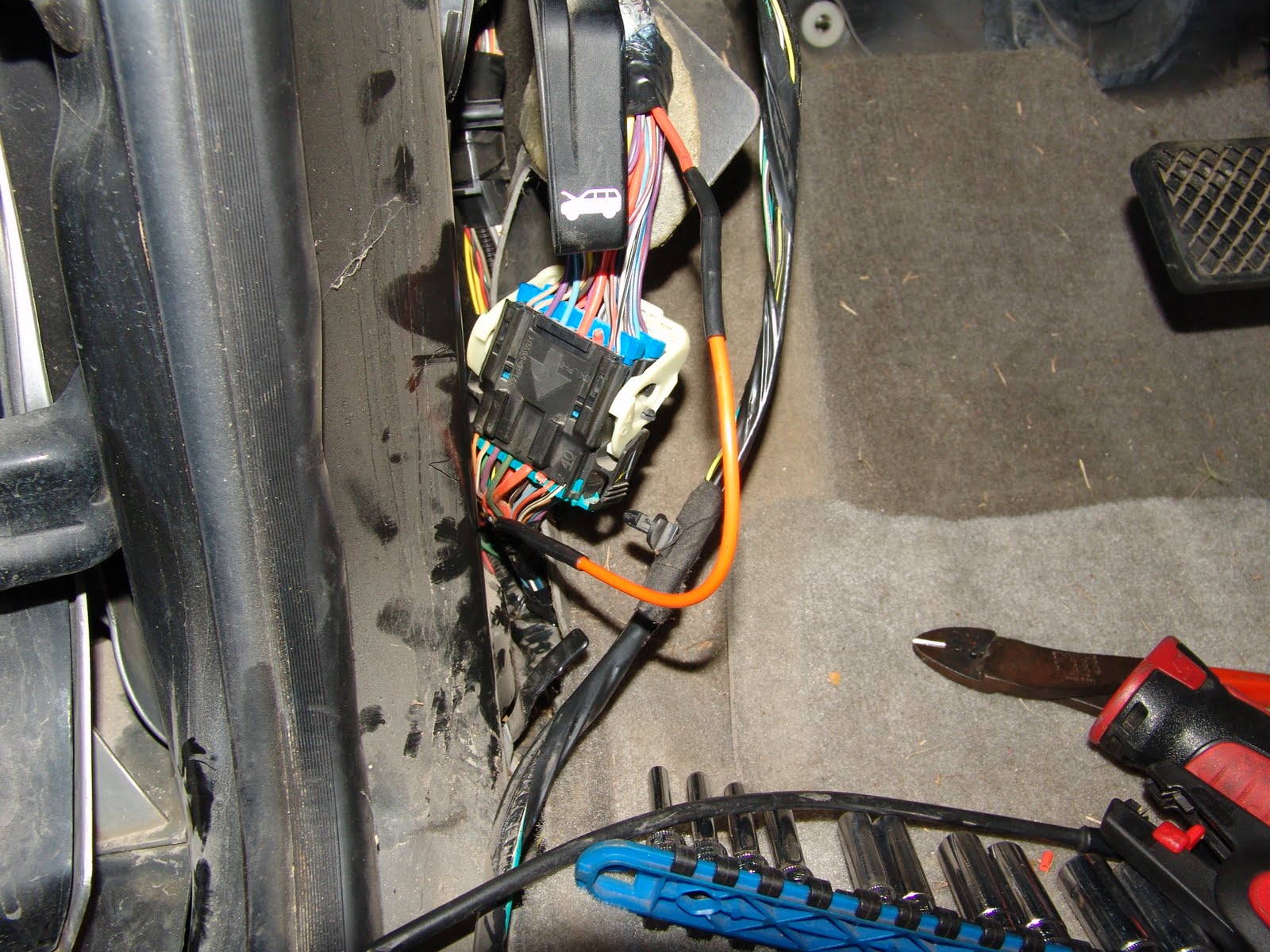
The next part of my testing was to perform the self diagnostic check of the system. To do this, I first had to locate the diagnostic connector. It is located to the right of the yellow connector, that is slightly left of center in the picture below.

The manual states to use a “special tool” into the diagnostic connector. The special tool is a jumper wire. I hooked up one of my fused jumper wires as shown below. The test actually begins with turn the ignition switch on (position II). With the driver’s seat belt unbuckled the seat belt reminder chime will beep 6 times. Next, set the ceiling light switch to the center position and close all doors. Now, we are supposed to install the “Special Tool”. I had previously installed my jumper with the fuse/circuit breaker removed and simply installed the fuse/circuit breaker at the appropriate time. I had surmised that this would be much easier to do than trying to install the connector, while sitting in the driver’s seat with the door closed.

After about 5 seconds the ceiling and spot lights were suppose to go into diagnostics and flash codes. This system would not go into diagnostics. After not being able to go into diagnostics, you are supposed to check for power and ground circuits, as outlined later in this post.

Testing begins at the underhood fuse box.

My Mitchell information system stated that fuse number 9 in the under hood fuse box needs to be tested. It is also listed on the cover as “Backup”.

I checked the fuse and it was good and had power on it.

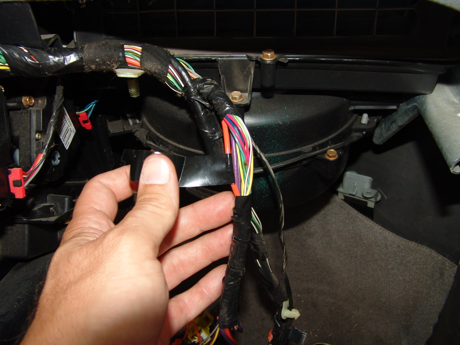
Going to the interior fuse box the instructions state to check fuse #10 (7.5 amp). It was good, so I dropped the fuse box down to do more testing. I checked for ground at the black wire (position #4) in connector “J” as shown below. It was good.

Next in the same connector, I checked for battery power at white/red wire, terminal “J2”. It was present. By the way that wire is supplied power from fuse #9 in the underhood fuse box. I have now confirmed that the the wire is good between the fuse #9 and this terminal.

Since the power and ground signals were all present and the multiplex unit would not go into self diagnostics, my conclusion was that the multiplex/fuse block unit was faulty. I installed a new unit (purchased from my local Honda dealership) and all systems were back working properly.

2002 Chevrolet Suburban, Radio Fuse Blows

This 2002 Chevrolet Suburban came in with the complaint that the radio fuse would blow. The fuse is in the driver’s side interior fuse box. I installed a new fuse and sure enough it blew when I switched the ignition on. I checked my wiring diagrams and found on this particular vehicle there was only the radio and the rear controls on that fuse. Possibly a short in the radio, kids do tend to put change in them at times. To pull the radio I removed the dash trim panel by unsnapping the edges. Dropped the tilt steering wheel down as far as it could go, switched the ignition on and dropped the shifter down to drive 1. This allows enough room to pull the trim panel out. Make sure the parking brake is applied and or you hold your foot on the brake pedal!!

To remove the radio the locking tabs on either side have to be depressed. Then the radio can be slid out of the dash. I unplugged the radio but the short was still there.

I looked under the dash to see if I could find a harness connector. My intent was to disconnect the rear controls without removing the whole center console. I found it deep under the center console area and figured it might be difficult to unplug. I regrouped and installed another fuse. I do this every time I move something in the process of locating a short. This keeps me from wondering what could have changed if the short goes away. By the way the short did go away. So I went back and looked at that harness closely and found the short. I had to remove the bottom dash cover.

I also had to remove the right metal brace as shown in the pictures below. I did have to bend the edge of the bracket closest to the steering column to remove it.

There it is. The green wire is what was blowing the radio fuse. The brown wire should have been blowing a fuse also as it has exposed wires. No arcing signs though.

Just a picture of the removed brackets and tools.

I pulled the harness some to get enough room to work on the wiring.

I wrapped each of the two damaged wires.

Then wrapped the whole harness that had been damaged.

Installed some good old split loom to further protect the wiring and this one was done.

2006 Saturn Vue, Short On 40 Amp Blower Fuse

This 2006 Saturn Vue came in with the complaint that the 40 amp fuse in the underhood fuse box for the blower would blow as soon as a fuse was put in it. This particular post is more about where I found the short at, rather than the disassembly process. On top of that this post would be a mile long if I included all of that. My hope is that either some one who reads this, or myself at a future date will be able to make a very easy repair by knowing where the problem might be and not have to completely remove the dash assembly. If you do need to remove the dash assembly and do not have the information already in a repair manual, you can purchase a subscription to either Mitchell or Alldata DIY from the ad links in the right hand side bar. Keep in mind also that even though this vehicle is a Saturn Vue, there are Chevrolet and GMC suv’s built on the same chassis. These vehicles also will be subject to the same short.

The following picture shows the actual shorted wire. The short is in the center of the picture. If you double click on it the picture will enlarge.

Once I had gotten to the short it was pretty easy to repair.


I wrapped the individual red wire several times.

Then I wrapped the whole harness.

For curiosities sake I wrapped the whole area with red tape. I wanted to know if I could see this harness without taking the whole dash assembly out.

This is the bracket that the wire was shorted out on. You can see the arc mark slightly left of center.

The backside of the whole dash carrier assembly.

I split a piece of vacuum tubing and installed it on the sharp metal edge of the bracket to protect the harness in the future.

After installing the dash assembly, I started looking for the red tape. You can see it through the passenger end of the dash.

There is a panel on the end of the dash that is easily removed and I believe that another short in this location could be fixed by working through the hole and under the dash. Taping may not be a possibility but sliding a piece of split loom over it, may be possible. I also think that a piece of split vacuum line could be installed on the sharp metal edge through the passenger end of the dash. When I get another one in, I hope to update this post. If you have this problem please leave a comment if you were able to fix it without removing the dash.

There is one other thing that will need to be checked either way the short is repaired. Behind the driver’s kick panel is a harness junction block.

The red wire terminals will be over heated and will need to be replaced.

Don’t forget you can double click on the pictures to enlarge them for better viewing.

In this particular case, I opted for bypassing the damaged terminals rather than replacing.

1996 Oldsmobile Cierra SL, Park Light Fuse Blows

This 1996 Oldsmobile Cierra Sl came in with the complaint that the park or tail light fuse would blow periodically. I did the usual inspection of all of the exterior bulbs and wiring. No problems were found. I was inspecting the wiring for the under hood light when I heard and arcing sound and saw a wisp of smoke. Two good signs I was at least in the right area. After thoroughly inspecting the under hood light wiring I found no problem. That is when I started thinking about what else could have shifted when I saw the smoke. Maybe the main harness had moved some. So I move the harness around. When I pushed down on the harness the fuse blew.

I pulled the harness up and inspected with a mirror.

A little bit better view of the short. If you double click on the picture it will enlarge so you can see the short even better. If you look closely you will see that the single park light wire was looped around the harness rather than going parallel with the rest of the wires. This was causing that one wire to support the weight of the whole harness and thus the short.

This is why I always try to keep small rolls of tape around. It is much easier to wrap around a short in a tight area.

All nice and wrapped up. I also slid some more split loom onto the harness for better wear protection.

I also slid some more split loom onto the harness for better wear protection.

Changing The Recirculation / Fresh Air Door Actuator Part 2

This 2004 Chevrolet Avalanche came in with multiple a/c problems including a code B0268, fault in fresh air /recirculation actuator assembly. This procedure applies to full sized Chevrolet and GMC trucks from 2003 to 2007 Classic. Avalanche, Sierra, Silverado, Suburban, Tahoe and Yukon. 1999 through 2002 Trucks would also be very similar. This post is starting after the dash cover is removed and all upper brackets are loosened and the lower corner bolts are removed. This allows the duct work to be moved around enough to work without having to remove the entire instrument cluster carrier assembly. The rest of the pictures , I hope are only temporarily lost in a failed hard drive. Now that everything is about out of the way, we are finally about to actually remove the The problem actuator. The bracket that I am pointing to needs to be bent over into the position shown.

This is a sideways view of the fresh air / recirculation actuator.

Normal view of the same actuator. You can only see where the wires go in this picture.

The screw heads are 5.5 mm.

I used a long 1/4″ extension and a swivel socket to remove the screws. It is also good to have a magnet to grab the screw before it falls. For the rear screw I went between the two plastic duct work tubes.

For the closer screw, I came in below the duct work.

I then had to wiggle my hand in to remove the actuator from the mount and door rod.

After maneuvering the actuator to a resting position to the left side, I had to switch hands to remove the actuator from the dash.

As you should be able to see by the blood on my hand there is something sharp in there. To order this actuator please click here.

As mentioned earlier, I have lost the rest of the pictures that would have shown how to remove all of the components up until the beginning of this post. The lost pictures also contain the ones that I need to show how to change the passenger side blend air door actuator as well. Good news I have had the opportunity to replace those actuators on other vehicles and you can see them by clicking here. 

I have had to change several of these actuators now and wanted to add some information. It seems that the actuator is difficult to remove and install on the door shaft on some trucks. I have found that using a long pry bar to the left of the opening to lift up on the duct work helps considerably.

This is the specific piece of duct work that is in the way.  There is also an insulator pad against the inside of the firewall that is in the way.

Sliding the pry bar under the duct work and the leading edge of the insulating panel then using the crossbar as a fulcrum gives just enough room to make the job much easier.

By this time you should have already removed the screws in the next two pictures but I just wanted to post them again as a reminder. Once those two screws are removed the duct work will move back and away from the alignment pin.

2005 Chevrolet Colorado, Blower Only Works On High Speed

This 2005 Chevrolet Colorado came in with the complaint that the blower only works on the high speed. None of the other speeds work. This is a very common problem and easy to fix. It is the same repair on Colorado’s and GMC Canyons. The blower resistor is located under the passenger side of the dash, to the left of the blower motor. To order parts please click here.

A 5.5 mm socket is needed to remove the two mounting screws.

If you look at the back of the connector you can see the change in the wire color caused by heat. Especially the blue wire.

If you double click on the picture below you can see the damage to the two center terminals.

I decided to remove the glove box and pull the wires up to make it easier to work on. I removed the three screws at the bottom edge of the glove box and it came right out. I disconnected the harness from the blower motor and pulled it right up. I did have to remove a harness hold down clip just behind the metal strip at the bottom of the picture below.

I started splicing in the new harness connector and noticed something missing. Do you see the difference between the two plugs?

The green seal is missing from the old connector. This is important in that in this application the seal is there more for shock absorption rather than sealing the connector from moisture.

I staggered the splice joints so that I would have a neat and tidy repair.

Then I taped the harness back up with electrical tape.

When I installed the new resistor and harness connector into the truck, I noticed that the harness hung down slightly and would be easy for someone’s foot to move the harness around.

So I pulled the blower motor vent tube loose and routed the wiring to the top side of the tube and rolled the harness up at the connector. This keeps the wiring as far away as possible from being disturbed. I recommended replacing the blower motor (blower motors drawing too much current have been known to kill the resistors) at this time but the customer declined. I can’t blame them as the motor is working well and the resistors are inexpensive, even if they do fail fairly regular.

If by some chance your blower motor does not work at all and the fuses are good, you may want to take a look at this ground buss bar connection behind the air filter assembly. It may not be bolted down, it may be loose or the connector itself may be burnt out.

A closer look at the ground buss bar connection behind the air filter assembly.

The wiring for the blower systems on these trucks is unusual for GM in that the resistor and the blower switch are on the ground side of the blower motor. The ground originates at the buss bar connector behind the air filter. Goes to the blower switch and is sent to the appropriate blower resistor terminal and then to the ground side of the blower motor. If a ground circuit is missing and the blower motor is good and connected, everything will test as having power on it.

2001 Buick Century, No Crank Condition

This 2001 Buick Century came in with the complaint that the starter would not work or if it did, it would make a scrapping sound. The customer stated that the condition would go away if the hazard lights were switched on. I had a very hard time believing this but I had the customer show me and it was indeed true. I also noticed that the dash warning lights and gauges would work erratically while it was displaying its cranking problem.

I looked at data with my Tech 2 and found ignition voltage values were low. Time to get to the ignition switch wiring. I unclipped the lower black hush panel. Removed the two 7 mm headed screws and unsnapped the plastic trim panel from the lower portion of the dash. Sorry no pictures. I then removed the remaining 7 mm screws from the interior metal panel.

Then, I switched to a 10 mm socket and extension to remove the four inner bolts.

Next, I removed the torx screws that hold the lower steering column trim cover in place.

With that out of the way, I looked for the pink wire coming from the ignition switch. I checked the voltage at the switch and as you can see it was very low. The starter would not work at all at this voltage.

I cycled the key again and the voltage came up some. The starter would work at this voltage but it made a terrible scrapping sound.

I checked power on both of the red wires at the ignition switch to make sure I did not have a problem with supply power to the ignition switch. It was good. Diagnosis of a faulty ignition switch.

The next step was to remove the screws at both ends of the dash for the dash trim panel.

Two screws above the instrument cluster and pulled the trim panel loose.

Once the trim panel was fully loose, the steering column has to be tilted fully down and the shifter handle has to be placed in drive 1. The top of the panel can then be rolled out of the rest of the dash. There is some flexing involved, so be careful not to break anything.

Now that that is out of the way, the top steering column cover can be removed.

There are supposed to be two torx screws holding the top cover to the column . Sometimes one, sometimes none. With the screws removed the cover can be flexed around to release the curved edge from the steering wheel.

Then continue sliding it to the side and over the lock cylinder.

One should have already disconnected the battery but if not go ahead and loosen the 7 mm screw in the center of the ignition switch junction block and separate the connector.

Now turn the key to the full crank position and depress the retaining pin as shown below.

Pull the lock cylinder out and set it on top of the column for reuse later. Be careful not to damage the two small white wires. They are part of the anti theft system and if broken the engine will not crank.

Depress the locking tab for the key buzzer switch, rotate and remove the switch.

Remove the torx screws that hold the ignition switch to the column.

Separate the combination switch connectors from the ignition switch connector.

Then carefully reassemble with a new ignition switch with harness assembly. I need to put in a picture of the whole switch assembly.

1991 Chevrolet Caprice Classic, Short In Park Lights

This 1991 Chevrolet caprice came in with the complaint that fuse #14 blows for the park / tail lights. As is normal for myself when looking for a short in the lighting systems, I went around the outside of the car and looked at the lights. There it was finally an easy one. The driver’s side headlight assembly was broken and was able to move around quite a bit.

The park light harness was touching sheet metal and there was a little bit of rust in the area.

I moved the wire a little and the short was gone.

After removing the socket from the light assembly, I removed the tape and found the short in the brown wire. Double click on the picture below to enlarge.

A quick fix with some electrical tape, along with reinstalling the split loom.

The split loom appeared to have been moved by someone trying to do an inexpensive body repair. This is about as good as it will get until a body shop gets involved though.

2004 Chevrolet Trailblazer, Changing Headlight Bulbs

This 2004 Chevrolet Trailblazer came in with the driver’s side low beam not working. This one is a little trickier than earlier models to replace the bulbs in, because the grill has to be removed first.

Not too hard though. There are several clips that hold the rill to the vehicle. Gentle prying with a flat blade screwdriver or similar tool will release most, with no problem.

A closer view. You can double click on most pictures and they will enlarge, however.

You can pry the ends out of the headlight assemblies also.

I do strongly recommend using a rag or thick tape to protect the light assembly from being scuffed.

I normally unsnap the middle portion of the grill and use my hand to work out the ends. This saves any damage to the lights. Not everybody will feel comfortable doing this though and that is why I showed how to do it with a screwdriver.

The grill coming out.

The grill out.

The bulb was blown but I also noticed some slight discoloration on the plastic so I opted to replace the harness connector while I was there. I had recently replaced a bulb in an Olds Bravada, where the connector looked okay and about two months later I had to change the bulb again along with the connector.

A new connector and bulb and this one was ready to put back together. If you need bulb connectors you can find the ones that I use at the following links.

Low Beam Connector

High Beam Connector

2001 Pontiac Grand Am, Changing Rear power Window Regulator & Motor Assembly

This 2001 Pontiac Grand Am came in with a rear window inoperative. Pretty clever use, of popsicle sticks and cardboard, to keep the window up though.

First, I removed the the phillips headed screw that holds the interior door handle bezel in place.

Then using a small screwdriver, I lifted the rear edge of the power window switch.

Disconnected the wiring from the switch.

Removed the door panel retaining screw from the open hole left by the power window switch.

Then, I removed the screw from the lower leading edge of the door panel pull handle.

Next, I removed the reflector lens with a small screwdriver.

Removed the last retaining screw.

Then pulled the door panel loose from the door. After all of the screws were removed the push pins were the only thing holding it in place. Double click on the picture below to get a better view of the clips and their positions.

Time to pull the vapor barrier loose. Be very careful to damage the vapor barrier as little as possible. After all it is what protects the inside of the door panel and switches from water damage.

The vapor barrier pulled back far enough to work on the regulator and motor assembly.

Removed the 10 mm headed screws that attach the regulator to the glass.

There are two.

Pull the glass up as secure out of the way. If you do not have suction cup cables, as I do, you can just get someone to hold it up.

Remove the 10 mm headed screws that hold the regulator to the door. Remove the regulator assembly from the door.

Slide the new assembly into the door and bolt in place. The regulator assembly should come preset in the proper position for reattaching the glass. Slide the glass down the track and onto the regulator bracket. Tighten in place.

There were three phillips headed screws that held the door panel to the door. The two black ones were the hidden ones and the silver one goes into the lower leading edge of the door panel pull handle.

The do it yourself glass retainers. Any more windows fail the owner may have to go on a diet 🙂