2007 Chevrolet Tahoe Cruise Control Does Not Work

This 2007 Chevrolet Tahoe came in with the complaint that the cruise control had been not working at times but now the situation had changed to not working at all. With or without a scan tool this is a very easy diagnosis. Checking the engine codes there was a code P0573 00 for a fault with the brake light switch circuit 1. The same basic test can be performed by checking to see if the stoplights are on with the engine running.

DSC09645

Going into engine data there is a data line that reads “Cruise Control Data”.

DSC09646

Within the cruise control data there will be a couple of lines starting with BPP which is short for Brake Pedal Position.

DSC09647

Note that BPP Circuit Signal reads applied with the ignition on and engine off.

DSC09648

BPP Signal also reads applied with the ignition on and the engine running.

DSC09649

The brake pedal is not depressed.

DSC09650

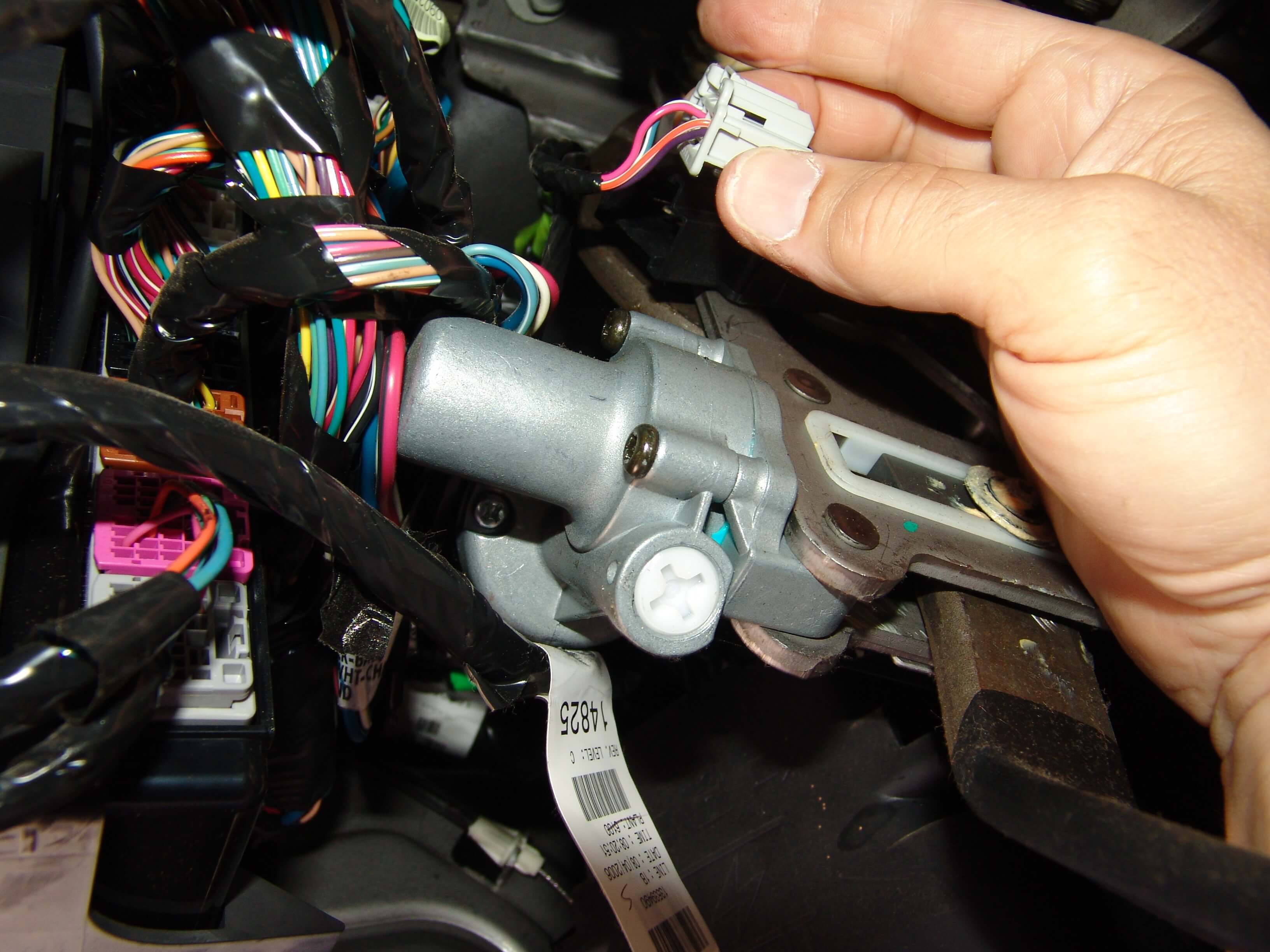
I removed the duct work shown in the next picture so that I could get better pictures for this article. I am holding the push pin retainer that secures it to the dash. It does not have to be removed to change the stoplight switch but it does make it easier to see.

DSC09651

The stoplight switch. Note that this vehicle has adjustable foot pedals.

DSC09652

The harness connector has a lever latch that has to be depressed in order to pull the harness loose from the switch.

DSC09653

The spring retainer has a latch that has to be lifted before the clip can be slid up and off of the shaft. It is pretty easy to get off but a bit of a pain to re install. I had to use a long narrow screwdriver (not shown) to depress the inner upper edge while at the same time using the small screwdriver (shown) to lift the outer clip edge (wedged) and my other hand to push the retainer down into the slot. Both hands involved and my head in the way so getting a picture was not possible. I should mention it was also 97°F and 85% humidity while doing this.

DSC09655

The switch can then be pulled down and off of the shaft.

DSC09654

The next picture shows the side of the switch that is visible while it is installed.

DSC09658

This shows the hidden side of the switch away from the retaining clip. Note that there is a slot in the plastic. This allows the switch to be removed without having to fully pull the master cylinder push rod off of the brake pedal shaft.

DSC09659

The stoplight switch has two switches built into it. One Normally Open (NO) and the other Normally Closed (NC).

The NO portion is supplied power on the Pink wire, terminal “A” with the ignition on only. The stoplights do not work unless the ignition is on. When the switch is activated by depressing the brake pedal, power leaves the switch on the Light Blue/White wire where it goes to the underhood fuse box and is then split and sent to the stoplights and to the ECM.

The NC side of the switch is supplied power on the Orange/White wire, terminal “C” from the BCM. It flows through the NC contacts when the brake pedal is at rest. It flows out of the switch on the Purple wire, terminal “D” back to the BCM. When the brake pedal is depressed the NC contacts open and break the circuit to the BCM. The BCM then transmits that information on High Speed GMLAN serial data bus lines to other modules affecting various functions.

Strangle enough today as I was putting this article together another Tahoe came in with this story. The customer was pulled over by a police officer and asked if he was riding with his foot on the brake pedal because the Tahoe’s stoplights had been on for quite a distance at highway speed. The owner informed the officer that he had not had his foot on the brake pedal for some time. The engine had been left running to keep the a/c working and they looked at the stoplights together and sure enough the stoplights were on and there was no one in the driver’s seat. The brake pedal was depressed a few times and the lights rechecked. They went out. The owner was given a warning and advised to have the vehicle fixed asap. Even though the stoplights were known to have been stuck on by at least two people there was no code P0573 stored. Instead there was a code C0161 00 stored in the EBCM. The customer had known that the ABS light had been on and there was also a message to check the Stabilitrak system. My assumption would be if the C0161 00 sets it prevents/blocks the systems from checking for conditions relevant to a P0573 00.

2012 Chevrolet Express Van Horn Stuck On Battery Goes Dead

This 2012 Chevrolet Express van came in with the complaint that the horn was stuck on and the the battery goes dead even though the horn has been disabled/disconnected. The customer could not accurately explain how the horn had been disconnected. I figured that the fuse or the relay must have been removed. The cover on the underhood fuse box is about a half pain in the rear to remove and install. To the left of the fuse box in the next picture is a narrow cover. There are two locking tabs. One at the top and one at the bottom.

DSC09614

DSC09613

The main cover has several more latches that have to be released. The two cover have to be separated in order to fully remove the cover.

DSC09612

I like to fully remove the covers because it gives a little more room and it allows me to actually read the fuse box legend.

DSC09611

The horn fuse is number 16 and it is a yellow 20 amp mini fuse.

DSC09610

It had been removed in order to stop the horn from blowing but it did not disengage the horn relay. In case you wanted to know the horn relay is built into the fuse box assembly and is not replaceable.  I am pointing to the fuse in the next couple of pictures….

DSC09609

…..so you can see where it is actually located. I had already disabled the horn relay from staying engaged and reinstalled the fuse so you would have a visual on it.

DSC09608

In diagnosing this problem I consulted a wiring diagram and TSB’s to see what all might be involved. After a review of the listed information I found that the horn switch and wiring, the BCM and an odd problem with phone apps installed interfering with the OnStar system. Experience was telling me it was most likely in the horn switch and/or it’s wiring. The horn switch and wiring is under the driver’s airbag so I needed to remove that starting with disconnecting the battery and then removing the lower dash trim panel. It is held in place by two bolts with 10mm heads along the lower edge.

DSC09600

There are also multiple retainers around the outer edge of the panel.

DSC09599

The instrument cluster trim panel needs to be held in place with one hand while you using the other to pull the lower panel loose.

DSC09598

There are four 10mm nuts securing the inner knee bolster.

DSC09597

There are also a couple of 7mm screws holding plastic bracket to it’s lower edge.

DSC09596

Once the last of the fasteners is removed the panel has to be wiggled around and twisted in order to remove it from the dash.

DSC09595

The backside of the knee bolster panel as it lays on the floor.

DSC09593

The yellow connector with the orange positive assurance clip is for the driver’s airbag. Pulling the orange clip from one end then allows the locking tab to be depressed. The battery had already been disconnected for about twenty minutes.

DSC09594

After the airbag connector was disconnected I loosened the 7 mm screw in the center of the in line connector block. Then pulled to two halves apart. Reconnecting the battery and installing the horn fuse no longer resulted in the horn blowing so I knew I was on the right track.

DSC09592

Next I needed to remove the airbag in the steering column. I used an 1/8″ Allen wrench to depress the locking lever through the side access holes. One each side.

DSC09602

I wanted to show you just what you are trying to depress with the Allen wrench. Notice the round hole just slightly left of center in the next picture. There is vertical rod inside the opening.

DSC09603

With the tool you need to push the vertical rod towards the center of the steering wheel. Then lift up on the airbag to release the clips.

DSC09604

In the next picture just above my thumb you will see the black plastic pin that locks into the hole mentioned above. Also note that I am pointing to the locking tab that secures the wiring harness to the airbag. It has to be pulled out first then the main connector can be pulled from the airbag. Be sure to follow the manufacturer’s instructions for handling the airbag properly. Remember it is an explosive device and can really inflict pain or even cause death if improperly handled.

DSC09605

Suspecting that the horn switch contacts were faulty I disconnected the harness that attaches to the top side of the airbag clock spring assembly. Connected the in line harness connector that was disconnected earlier and the horn would still blow. This proved that the problem was between the in line connector and the internal workings of the clock spring. So much for a simple faulty horn switch. Since I was already here I decided to go ahead and remove the steering wheel so that access to the remaining parts would be easier.

DSC09580

Pulling the steering column requires a set of special “j” style bolts that work in combination with my standard steering wheel puller kit.

DSC09581

The “J'” bolt has to be inserted into the slot on either side of the steering wheel.

DSC09582

Then rotated so that the arrow points inward towards the shaft. Repeat with the other bolt and remove the wheel with the puller.

DSC09583

The steering column covers can be removed without pulling the steering wheel but it is easier with it removed. Also at this point I was pretty sure the clockspring assembly would need to be replaced.

DSC09591

The tilt lever handle has to be pried loose. If your grip is strong enough you can just grab a hold of it and pull it loose.

DSC09607

DSC09606

DSC09590

DSC09589

I disconnected the 10 cavity harness connector from the underside of the clock spring assembly and the horn no longer blew proving that there was an internal short to ground inside the assembly.

DSC09587

From this point the snap ring holding down the clock spring module was about all that had to be removed to finish changing the part.

DSC09584

There was a wire tie that had to be removed and replaced as shown below. There also is a reusable harness clamp that has to be opened to remove the harness from the column.

DSC09588

Before removing the steering wheel and/or the clock spring assembly make sure the front wheels are pointed straight forward. The new part comes pre timed and locked to this position. 

DSC09586

Once the new part is installed the orange tab needs to be broken off as shown below.

DSC09585

Another successful repair. As always remember to “Stop Guessing and Start Testing”.

2006 Chrysler Sebring Convertible Multiple Electrical Problems

This 2006 Chrysler Sebring came in with several electrical problems but the chief concern was that the alternator was not charging. The customer also stated that the wipers did not work and that the check engine light has been on for a while. Codes P0135, P0141, P0155, P0161 and P0622 were stored. The first four codes were for oxygen sensor heater circuit faults and the code P0622 is for a fault with the generator/alternator field control circuit.

Testing for the code P0622 and the resulting no charge condition begins with connecting a test light across the two terminals at the alternator harness. If you have a scan tool you can actuate the field driver circuit and check for a flashing light at the installed test lamp. Without a scan tool you will need to make sure everything is safe and secure. Then have the engine started while observing the installed test light. It should be illuminated to some degree. Turning on the headlights and air conditioner will cause the light to burn brighter. In this case there was no light so further testing would be needed. There was power on the green wire with the ignition on and the engine off. It varied between one and three volts. There was no ground present on the black wire.

DSC09639

I used a backprobing pin to check the continuity to ground on the black/tan wire. It was about 60 k ohms. For all practical purposes it was an open reading. I normally do not even bother checking for ohms of resistance in a circuit like this because the results can be deceptive. I also need to remind you and myself to always consult a wiring diagram to see how a system operates. I am very accustomed to Chrysler products using an “A” circuit field system where positive voltage at the field is constant and the negative side is controlled by the regulator (inside the PCM in this case). This vehicle uses a “B” circuit field system that has a constant ground circuit applied and the regulator varies the positive side of the field circuit. My initial reading were throwing me off and looking at a wiring diagram straightened me right up. 

DSC09640

Back to the repair at hand. I know that I do not have a ground on the black/tan wire at the alternator field connector. I also know that the wire is supposed to terminate at ground position G103 located at the inner left shock tower. Looking with a flash light I could see the G103 connection point but several things would have to be removed in order to have access to the wiring. The air filter housing, the intake boot/hose, the cruise control servo and an emissions solenoid would all have to be moved out of the way.

DSC09638

You can see the emissions solenoid to the left of center and it’s bracket to the right of center in the following image. You will also notice an absence of images related to the actual wiring repair. The reason being is that these wires are in a very awkward position for a 6 ft man to be repairing. Balancing my chest on the driver’s side radiator support while trying to work both arms and hands in an area that is much narrower than the width of my shoulders. Also coordinating my feet in this semi prone position so that I do not slide off of the car. So there was not enough time, room or inclination to take pictures while this repair was active.  Since there were about ten wires of various sizes involved at this ground point I decided to separate them into two groups and used 10 gauge terminals and wires to bring it all together. The terminals I used were  non insulated. I used heat shrink tubing to insulate the terminals. I also used a silicone sealer where the multiple wires entered to joint. If you do this make sure that your sealer is not corrosive to copper. Generally sensor safe silicone sealers are okay. I actually stripped some wiring in several places then sealed the bare wiring with silicone sealant and tossed to the side for a couple of years. Every three to four months I would peel the silicone off of a section of bare wire and inspect for damage. There was never any sign of the sealer attacking the bare copper wiring. If you do wiring repair I suggest you do the same test with whatever sealer you choose to use.

DSC09632

The G103 ground point re established. Not the position of the splice connections in the background. Before buttoning this one up I made sure that the siliconed side of the connection was pointing down so that if any water was to get near the wiring it would have to flow uphill to penetrate the connection.

DSC09634

I also removed the rust from the attaching bolt in my glass bead cabinet. A wire brush and persistence will work though.

DSC09636

When I opened the tabs that secured the wire insulation the terminal fell off because the wire had completely corroded loose.

DSC09644


DSC09643

The attaching bolt before I cleaned it.

DSC09631

This vehicle had the battery, alternator and alternator harness replaced before arriving at my shop and it did not need any of them. Just a reminder to “Stop Guessing and Start Testing”.

How To Search Sparky’s Answers; Old School, New School or No School?

No matter which category you fit into Sparky’s Answers has a search option for you. Try all three methods. You might find out that you are not who you think you are.

Old School

Old School fits me because well, I am old. I grew up in this industry and this world using a table of contents or an index to find the information I needed within printed material. Give me a list of what is in the book and let me decide what is important to me. With that mindset, I prefer to use the “Repair Article Index” as my first option for looking for a particular article within this site.

There are a pros and cons to this method though.

It displays and works well on all devices however my older eyes prefer viewing it on the larger screens.

For better results you should know what you are looking for and how it relates to the index list.

For example, the auto blower system on a 2003 Silverado is exactly the same as the auto blower system on a 2004 Sierra, 2005 Avalanche, 2006 Escalade and so on. I know this, so I only have to look under Full Sized GM Trucks & SUV’s, Front HVAC,  Blower Issues and Auto Controls. Once there I have access to every article related to that topic regardless of the model, year or problem.

This is both a good and bad thing. If you are well informed about shared components/technologies within a manufacturing group then you will be able to use the repair article information across various brands. This is also good if you are just generally curious.

The bad part is if you do not have the above background knowledge or experience you might easily overlook relevant information about your vehicle’s problems.

old_school_menu_1

old_school_menu_2

New School

New School uses the “Find An Answer” drop down search menu. Simply enter the “Year”, “Make”, and “Model” and let the system find the articles related to that vehicle for you. The drawback to this method is that you may not realize that there may be multiple repair articles that you would like to read, but the system did not recognize them because of the search parameters you entered. Over the next year this system will be refined to include related articles about similar vehicles and more levels of search will be added.

It does work really well on a smart phone though.

new_school_menu_1

new_school_menu_3

new_school_menu_5

new_school_menu_6

new_school_menu_7

No School

What I refer to as No School is the “Search Bar” found at the lower edge of the “Find An Answer” section. If you are relatively new to automotive repair or just have not had any luck using the other two methods start entering keywords to search for your answer. The shorter the keyword phrase or list is the more likely you are to receive a result.

no_school_menu_1

There is no perfect solution so for the time being Sparky’s Answers offers these three methods for searching for repair article information.

2007 Chevy Express G1500 Van, Fuse #10, HVAC Fuse Blows

This 2007 Chevrolet Express G1500 van came in with the complaint that the A/C would not work. Neither the blower nor the compressor would come on. Looking at a wiring diagram revealed that fuse number 10 in the interior fuse box supplies power to both the compressor and blower control portions of the HVAC system.  The interior fuse box is located under the driver’s seat.

DSC00088

Fuse #10 listed as the HVAC fuse, 20 amp.

DSC00094

The position of fuse #10 in the fuse box legend.

DSC00091

Fuse #10 in the under seat fuse box.

DSC00089

It was blown. Now to figure out why?

DSC00096

Since the bulk of the HAVC system components are located under the hood on the passenger side I decided to take a look there first. I removed the coolant overflow tank that is secured with a 10 mm headed bolt.

DSC00076

Looking down at a harness that runs across a metal a/c line I could see that the split loom was broken and separated. I also could see the dark residue left over from the plastic rubbing on metal.

DSC00077

Placing a mirror under the wiring harness I could see that the wire insulation had be damaged.

DSC00081

It took some effort to rotate the harness around enough to see the damage without the mirror. I always try to visually confirm the location of a shorted wire before moving a harness around very much because many times the movement will cause very small insulation wounds to disappear. That in turn makes it difficult to guarantee the repair.

DSC00080

I removed some of the harness tape and split loom from the damaged area.

DSC00082

Separated the damaged wire.

DSC00083

Wrapped it and then the harness with electrical tape.

DSC00084

Installed new split loom with the split rotated away from the metal a/c line.

DSC00085

Drilled a hole in a flange on the blower case.

DSC00086

Then secured the harness with a wire tie to the blower case so that it could not come anywhere near the a/c line again.

DSC00087

2002 Toyota Highlander Temperature Stuck On HVAC Control Head

This 2002 Toyota Highlander with automatic temperature controls came in with the complaint that the air conditioning controls head was stuck at 84°F in the middle of summer. The setting would not change regardless of control movement. The system was putting out hot air also.

DSC00874

The trim panel around the HVAC control panel is secured with plastic spring tab clips. I used a plastic pry bar  at the location below to work the panel loose.

DSC00872

Then proceeded to do the same around the rest of the panel.

DSC00873

A view of the plastic retainers.

DSC00871

There are multiple screws around the outside edges of the HVAC control head assembly and the radio that have to be removed.

DSC00870

One kind of test that I discovered was that if the harnesses are disconnected from the HVAC control head and then reconnected after a slight wait time…..

DSC00868

…..the panel would reset to 75°F. The vent temperatures also adjusted to the cooler setting. This along with some research into the issue confirmed my suspicion that there is an internal problem in the HVAC control head.

DSC00869

The control head and the radio need to be separated at this point. I removed the two upper screws shown below as well as their counterparts on the opposite side.

DSC00867

I then flexed the bracket enough to separate the two components.

DSC00866

Not exactly sure why I took this picture but it does show that the two parts can be separated after the attaching screws have been removed.

DSC00865

I found a vendor that would repair the HVAC control assembly and shipped it off. They also offered an exchange unit but the cost was obviously higher. My customer was more than willing to wait a few extra days to get his Highlander back in order to save $150 USD. When it returned everything worked as it should. We were very happy with the repair service.

DSC00875

2005 Acura RL Battery Goes Dead While Parked

This 2005 Acura RL came in with the complaint that the battery would go dead if the car sat parked for more than three days straight. The battery had been replaced a couple of times already. I first connected a jump box connected in parallel to the battery before installing  the meter as shown below. You cannot see it but the black lead is installed in the COM socket and the red lead is installed in the 10A socket. The dial is set to read DC amps. After an hour there is still a .23 amp drain on the battery.

DSC09535

Because I have been down this road before I consulted a wiring diagram first to see which fuse supplies battery power to the HFL module (Hands Free Link). It turned out to be fuse number 5 in the driver’s side under dash fuse box. Pulling the fuse removed the drain. Pulling the fuse will also activate the anti theft feature in the radio so do not pull it or fully disconnect the battery unless you have the reset codes. 

DSC09536

Testing across the fuse terminals had shown a 2.3 millivolt drop confirming there was a drain on that fuse. Sorry that I could not take a picture of this test. Just not enough room and awkward angles to work with.

DSC09538

I looked in my component locator system and found that the HFL module is located behind the right kick panel area. I started by pulling down the passenger side underdash hush panel. It is just snapped into position with two alignment pegs at the firewall edge.

DSC09548

Disconnected the harness connector for the courtesy light and removed the panel.

DSC09547

Lifted the inside edge of the rocker trim panel to begin releasing the clips.

DSC09545

Worked my way from the front to the rear of the trim panel.

DSC09544

Pulled the door seal away from the kick panel.

DSC09543

Pulled the kick panel loose from the body. Note the two clips that secure the panel to the body. Those rarely come out and stay in the panel. I had to remove those separately and reinstall them into the kick panel.

DSC09542

Now if you look above the passenger side interior fuse box location you will see the lower left corner of the HFL module. It is secured to the body with one 10 mm nut which is a little bit of a pain to remove. Not even sure if it has to be removed to disconnect the green harness connector but I wanted to make sure you had a good view of the actual part.

DSC09540

Since the battery had been connected during all of my testing the HFL module was warm to the touch.

DSC09539

With the HFL module disconnected the standby drain dropped to an acceptable .03 amps.

DSC09549

As in most cases the vehicle owner never uses that system so they elected to leave it disconnected. I did leave it installed in the car but electrically disconnected.

2007 Lincoln Town Car HVAC Actuator Replacement

Now that the Dash Assembly is out of this 2007 Town Car it is time to start changing actuators. The image below is of the backside of the dash assembly. In the very center of the picture is the mode housing. If you look to the right edge you should notice a white round piece of plastic. The Panel/Defrost Mode actuator is located directly above it. To the left of center you should notice a third slightly smaller duct opening. The Floor/Defrost Mode actuator is located directly above that opening. Both actuators have a six cavity harness connector with only five wires installed.

DSC09498

Okay by this time I was about done with this project so there are some gaps in the steps as far as pictures go. From the front side of the dash behind the radio opening there are two black screws with 7 mm heads that have to be removed. They secure the center mode duct work assembly to the main dash assembly. Notice at either end of the dash assembly are a face vent opening and a smaller side window defogger vent.

DSC09426

Going back to the back side of the dash assembly. On the right side in the next image there is a metal bracket above where the steering column mounts. It is held in place by a single 11 mm headed screw. To the left above the glove box opening there is a metal bar that is held in place by a single 8 mm headed screw. Now that those are out of the way the left and right duct assembly tubes can be removed. They are all held in place by multiple 7 mm headed screws with a coppery color and are attached to plastic supports.  There are two or three 7 mm screws that are black in color that attach the ducts to lower metal brackets. It is very important to return the screws to their proper locations during reassembly due to a difference in thread design.

DSC09498

No that all of that other stuff is out of the way the center mode duct housing can be pulled from the dash assembly. The defrost ducts will still be attached. There are four screws with 8 mm heads that hold the defrost duct work to the main mode assembly. Two are located at the top rear edge and two are located on the face side of the assembly.

DSC09497

The defrost duct work can now be separated from the main housing.

DSC09496

DSC09495

The Floor/ Defrost Mode actuator is located on the glove box side of the housing. All of the actuators are attached with 8 mm screws.

DSC09494

The Panel/Defrost Mode  actuator is located on the steering column side of the duct. Note that the white aspirator tube has been removed to access the mounting screws.

DSC09492

The next image shows the Fresh Air/Recirculation actuator that is still mounted in the vehicle. The dash assembly Does Not have to be removed to change this actuator.

DSC09434

To the left of the glove box opening is the Passenger Side Temperature Blend door actuator. Again the dash assembly Does Not have to be removed to replace this actuator.

DSC09433

To the right of the steering column area is the Driver’s Side Temperature Blend door actuator. I Think this can be changed without removing the dash assembly. It would be a little difficult though so I replaced it while the dash was already out and it was easy to access.

DSC09432

The new actuator installed above the white aspirator tube.

DSC09425

Now all I have to do is put it all back together.

DSC09426

If one was to try and change the driver’s side temperature door actuator the lighting control module would need to be removed first. It is shown in the next image. Keep in mind that the view would be from the gas pedal looking back towards the driver’s seat. Note the white aspirator tube just above it.

DSC09423

The driver’s temperature blend door actuator would be located just forward of the white aspirator tube.

DSC09417

The passenger side temperature door actuator (left) and the fresh air/recirculation (right) actuators.

DSC09419

2007 Lincoln Town Car Dash Removal Part 2

Now that the Steering Column has been removed and Part One of The Dash Removal has been completed the focus can be turned to the lower connection points. The rocker/kick panel trim cover can be removed by lifting the inner rear edge and shown below. This will release the spring clips that hold it to the floor.

DSC09490

Then at the kick panel area it can be pulled towards the rear of the vehicle to release those clips.

DSC09465

There are two main inline harness connectors that have to be disconnected. The upper black connector has two locking levers at the rear of the connector that prevent the white locking bar from moving. After they have been depressed the lever can be rotated towards the front of the vehicle. The white connector withe the gray locking bar has a push button latch just behind the center of the gray locking bar. On both connectors once the locking bars are fully rotated to the unlock position the connectors will need to be pulled firmly to separate the inline harness connections.

DSC09500

There are two ground point locations that are secured by bolts with 8 mm heads.

DSC09501

All of the connectors disconnected.

DSC09430

Under the hood on the driver’s side of the firewall there are two connectors. The larger connector must be removed. There is a securing bolt in the center of the connector body with a 10 mm head.

DSC09514

There are two fasteners that hold the driver’s side of the dash assembly to the body. Both have 15 mm hex heads. It is kind of hard to focus on but I have a deep well socket and extension installed on the 15 mm nut in the next image.

DSC09519

The same socket and extension installed on the lower bolt.

DSC09518

The shifter cable is attached to the rear of the dash assembly where I am point to in the next image.

DSC09517

The clip that cannot be seen on the rear of the metal bracket attaches around the rubber location sleeve on the cable.

DSC09516

After the connector has been pulled loose and moved out of the way the latches that secure the inner connector to the firewall will need to be depressed and the connector body pushed to the inside of the vehicle.

DSC09499

On the passenger side of the dash the next image shows that the kick/rocker trim panel has already been removed. The black and gray harness connectors have been separated.

DSC09503

There is also an antenna lead that has to be separated and another ground terminal bolt removed. For some reason I do not have clear images of two fasteners that need to be removed from this general location. There is a 10 mm hex nut in the top right corner of the next image. It is right at the shadow line. Also there is a bolt with a 10 mm head that is to the right of the glove box opening that secures the dash assembly bracket to the body side wall. 

DSC09502


To the right of the gas pedal area there is a small carpeted trim panel with a push pin fastener securing it to the inner bracket.

DSC09506

With the trim panel removed and the carpet access panel flipped back the four 13 mm nuts can be removed that hold the lower center support bracket in place. At this point the dash is loose and care should be taken to make sure it stays in position while the last of the prep work is done. 

DSC09453

There is a connector for the SRS module that needs to be disconnected behind the lower center support bracket location.

DSC09505

There is a single lever/thumb latch at the top of the connector body that has to be depressed before the connector can be removed from the SRS module.

DSC09504

At this point the dash is loose and ready for removal. It can be done by one person but it is much easier with two. That is why there is no picture of the actual removal. Note that I have installed covers over the seat. I found it easier to remove the assembly out the driver’s door opening. We rolled the dash assembly down and rested it against the seat. I got a good grip on it from the driver’s seat position while my assistant worked from the passenger side of the vehicle. We lifted and moved it out of the vehicle in unison in stages.

DSC09427

The dash assembly out and laying on multiple fender covers on my shop floor.

DSC09426

A look from the passenger side of the vehicle.

DSC09420

2007 Lincoln Town Car, Dash Removal Part 1

Time to remove the dash assembly from this 2007 Lincoln Town Car. I had previously diagnosed a faulty Panel/Defrost Mode Actuator and removed the Steering Column Assembly. Now it was time to move on to the main dash assembly. There are two actuators on this vehicle that cannot be changed without first removing the dash assembly the Panel/Defrost Mode actuator and the Floor Mode actuator.

I removed the actual instrument cluster in order to lighten the load and because they are relatively fragile. The shift indicator cable had already been disconnected during the process of removing the steering column.

DSC09515

There are four 7 mm headed screw that secure the cluster to the dash panel/carrier.

DSC09509

Once the screws are removed the cluster can be maneuvered around to gain access to the harness connector. The gray lever shown below would have been all of the way to the right and laying tight against the connector body. There is a latch that has to be depressed so that the lever can be lifted and rotated to the left position.

DSC09508

When the lever reaches the full left position it will begin to lift the connector body from the instrument cluster assembly. The terminals are delicate and care should be taken to keep the connector from moving any direction except straight up.

DSC09507

The clock and radio do not have to be removed first in order for the dash assembly but they will need to be removed later to gain access to the screws holding the duct work in place. They are easier to remove while the dash assembly is still in the car and it will make the assembly lighter. Two screws hold the top edge of the clock in place. Then the clock has to be firmly pulled from the dash as it is still held in place by two spring clip retainers.

DSC09513

There is one harness connector at the rear of the clock assembly.

DSC09512

There are two screws behind the clock that secure the upper edge of the radio assembly. There are two more screws at the two lower corners. All of the retaining screws for the clock and the radio have 7 mm heads.

DSC09511

On this Town Car there were two electrical plugs and on antenna lead attached to the rear of the radio assembly.

DSC09510

Now the “A” pillar trim panels have to be removed. The door seals in that area should also be pulled loose from the body lip.

DSC09463

I find it easier to pull the panel from the top edge and bring in down towards the seat in order to free the spring clip retainers. The panel can then be rocked back and forth and ultimately lifted from the corner of the dash.

DSC09464

Now that the “A” pillar trim panels are removed the forward dash panel cover can be lifted from one corner.

DSC09462

The lifting motion can continue across the dash until the panel is fully loosened.

DSC09461

Care should be taken to lift this panel high enough to clear the main dash assembly so that the clips will not drag across the softer dash surfaces.

DSC09529

There are a total of three screws with 7 mm heads and one screw/bolt with a 10 mm head that attach the top edge of the dash assembly to the body. The three 7 mm headed screws are longer than any other similar screws in the dash and should be kept separate for proper re installation later.

DSC09455

The passenger side underdash hush panel is held in place with three push pin retainers. A tool can be used to pull them loose but I just pulled the panel down by starting at one corner and working my way across. Once these pins get older and more brittle that will no longer work. Yes this car is nearly ten years old but it has been garage kept most of it’s life so all of the plastics are in better shape than most.

DSC09528

The panel drops down and the courtesy light socket can be twisted loose and removed.

DSC09527

After opening the glove box the sides of the inner compartment need to be pulled in to release the stop pins. I do this because I need the extra room for the next step.

DSC09525

The cable stop attaching pin will need to be removed from the side of the glove box. Not easy to see but there is a small detent on the lower edge that has to be released and then the pin can be slid down to the larger slot for removal.

DSC09526

There are two 7 mm headed screws that hold the glove box hinge bracket to the dash. When reinstalling pay attention to the two nearby holes that have alignment bosses around their inner circumferences. Snug the screws and wiggle the hinge bracket around while applying a slight upward pressure. Until you feel them drop into position.

DSC09524