2002 Buick Rendezvous Water In The Tail Light Assembly

This 2002 Buick Rendezvous came in with the complaint that the left rear turn signal did not work. Also the stoplight and the tail light on the left side did not work. Well three inches of water and the glass part of the light bulb in the bottom of the tail light assembly was pretty clear evidence of why it did not work.

After lifting the rear hatch the retaining screws for the light assembly could be removed.

With the two phillips headed screws removed the light will slide straight back. It may take some bumping to allow it to come free of the body.

The next picture shows the slide clips that secure the front edge of the light assembly.

The main harness connector is disconnected by first lifting the thumb latch and then pulling the connector halves apart.

Since this vehicle is twelve years old and has nearly 250,000 miles on it the customer was not interested in replacing the lamp assembly. I located the lowest portion of the lamp assembly and drilled a couple of small drain holes.

After allowing the water to drain form the assembly I realized that I had not chosen to lowest spot on the assembly.  Inside this channel is the lowest spot. I had to be careful and make sure that I angled the drill bit away from the red outer lens.

I was expecting to have to replace the light bulb socket in this vehicle due to rust and corrosion but in the end I was able to fully dry everything out with shop air and sunshine, fill the socket cavities with dielectric grease and install new bulbs.

The lights are no back working properly.

There was some staining from the water that had been sitting in the bottom of the light assembly.

You can however see the difference as compared to when it had water in it.

2001 Chevrolet Tahoe Air Conditioner Is Not Very Cold

This 2001 Chevrolet Tahoe came in with the complaint that the air conditioner was not cooling properly. The compressor was on and the blower was working. The air coming from the dash vents was cold but the volume of air was low. Too low for comfort on a warmer day. I was pretty sure from the description and the “feel” of the system that the cabin air filter was restricted.

To access the cabin air filter the passenger side under dash hush panel has to be partially removed. There are two 7 mm headed screws that need to be removed. The one shown below and there is one more towards the center of the panel. The third screw over the transmission hump does nor need to be removed.

With the hush panel dropped down you can see the inch and a half wide strip that is located on the bottom of the HVAC case between the blower resistor and the evaporator core. There is a single 5.5 mm headed screw at the rear of the strip that holds it in place.

With the cover strip removed leaves fell out of the case. Some when the cover was removed and the rest when the filters were pulled out of the case.

From the looks of the cabin air filters they were most likely the originals to the truck. Thirteen years of build up.

I took my home made vacuum cleaner adapter (5/8 heater hose attached to a cone adapter) and vacuumed the rest of the debris from the HVAC case.

There sure is a big difference between the old and the new cabin air filters.

When installing the new filters, slide the first one straight up and into the box.

Then push the filter towards the front of the truck until it stops and is positioned as shown below.

Now the second filter can be installed.

With the new filters installed into the HVAC case the strip cover can be re installed. The outer edge hooks into place and then the strip is pivoted up so that the retaining screw can be re installed.

I had heard excessive noise and felt a vibration earlier when checking the system out so I needed to remove the blower motor and check it for debris. The harness connector as shown below is almost impossible to disconnect. The thumb latch has to be depressed but you cannot see it since the connection point is under the blower motor hush panel.

I remove the two 5.5 mm headed screws that hold the cover in place and then position it so that I can access the harness connector latch .

Once the harness has been disconnected and the cover removed the blower motor can be removed from the HVAC case. If you look at the blower motor below you should be able to see a tab at the 9:30 position. That tab has to be flexed down so that the blower motor can be twisted and removed.  For a more detailed explanation of removing the blower motor please click here.

There were quite a few leaves in the impeller blade.

DSC09917


This is a better view of where the harness connector fastens to the blower motor socket.

2002 Buick Rendezvous No Run Condition

This 2002 Buick Rendezvous came in with the complaint that it would not run at times. Started out just a problem sometimes but now it is most of the time. I checked for codes and the only one present was for a fuel level sensor. I checked fuel pressure and spark and they were both present. After doing an injector balance test (passed) with my Tech 2 scan tool the engine fired and ran for a few seconds. So the base problem was no injector pulse while cranking the engine. I made sure there was no anti theft codes current and there were not.

After looking over service information I decided to look at the cam (CMP) and crank (CKP)”A” sensors. In checking for power and ground at the CMP sensor harness connector I found that there was no 12 volt supply on the red/white wire. During my research I read that the CMP and the CKP “A” sensor shared a PCM internal driver although they are connected to two separate external wires. I disconnected the harness connector for the CKP “A” sensor and power came back to the CMP sensor harness. I was about to condemn the CKP “A” sensor as shorted when I noticed a problem with the wiring just behind the a/c compressor.

I disconnected the harness that went to the compressor and pulled the whole harness down for a good inspection. There were multiple raw wires and it appeared that some had been touching each other. The light green wire is the 12 volt power supply from the PCM to the CKP “A” sensor. By the way this sensor is also known as a 24X sensor.

I separated the wires and and replaced the damaged areas one at a time. I made sure to stagger the joints so the the harness would go back together neatly.

I installed some split loom over the wiring to add some protection to the harness.

A pretty neat job even if I do say so myself.

Now I have a nominal 12 volts back at the red/white wire at the CMP sensor. I also had the same voltage at the light green wire at the 24X sensor.

I reconnected all of the wiring and the engine started right up. The wiring had been damaged by years of sloppy oil changes. The oil collected in the harness right at a turn and stayed there. As a result the insulation merely dissolved, leaving the wires exposed to each other.

2009 Buick Lacrosse Interior Light Fuse Blows

This 2009 Buick Lacrosse came in with the complaint that the interior light fuse blows. The fuse is located in the passenger side interior fuse box. there is a cover on the end of the dash that covers the fuse box.

I confirmed that the interior light fuse was blown. The fuse should be labeled INT/ILLUM on the legend that is on the inside of the cover panel.

I installed a fused jumper wire that uses the cheaper ATO/ATC fuses. The fuse again blew.

After looking at wiring diagrams I realized that this fuse goes straight to the BCM and the BCM send power out on multiple leads.  I figured that the BCM area was going to be the best place to start testing. The BCM is located under the driver’s side of the dash. The under dash hush panel and the knee bolsters have to be removed to access it.

There were a couple of push pins that held on the under dash hush panel.

A side view of the push pin.

There are two screws on either side of the outer knee bolster panel that need to be removed. The screws have 7 mm heads.

There are spring clips that have to be dislodged by pulling the upper portion of the panel towards the driver’s seat.

There are a total of four 10mm headed screws that hold the inner brackets to the dash.  The forward one is accessed a shown below.

The rearward screws are accessed through the round holes on either side of the panel.

There are about half a dozen 7mm headed screws that attach the outer panel to the dash.  After removing the panel I installed a new fuse to confirm that nothing had changed.

The fsue did not blow this time and the interior lights were working properly. A closer visual inspection under the dash found these two shorted wires for the driver’s footwell light. Notice the raised aluminum mounting boss with a threaded hole. That is where the forward bolt attaches the panel to the dash carrier.

I separated the two wires.

Then cut out the bad spots and spliced the wires back together. I checked first to make sure the light would still mount in it’s holder with the wires slightly shorter. Probably could have cut out a couple of inches if I had needed to.

After I had sealed the connection with heatshrink tubing, I installed a piece of split loom to protect the harness.

I also made sure that the harness was out of the way of the bracket when I re installed the metal knee bolster.

2007 Nissan Maxima, Gas Gauge Stuck On Empty

This 2007 Nissan Maxima came in with the complaint that the gas gauge was stuck on empty. Actually a closer look revealed that the gauge needle was stuck under the empty stop peg. Due to the coloring of the instrument cluster lens I was unable to get a picture of this before disassembly.

If you have a strong magnet you can use it to move the gas gauge needle into the correct position. If you do not have strong magnet or if you just need to know how to remove the instrument cluster, continue reading.

The top cover over the instrument cluster assembly is held in place by spring clips as shown in the next picture. To unfasten the cover lift up to release the clips. Note that there is a tether cable that attaches the cover to the dash carrier. It does not need to be removed. In fact I do not even know if it can be without damaging something.

There is one phillips headed screw behind the middle of the assembly that needs to be removed.

I was also hoping that the other two phillips screws were all that was left to remove the instrument cluster. They do have to come out for the final disassembly to correct the needle issue but not now.

I could feel something holding the bottom of the instrument cluster so I wanted to remove the covers under the steering column. Removing the fuse box cover reveals ons crew to the left.

It has a torx head. There is also one other matching screw under the right side of the panel.

I am not sure if the inner steel panel actually has to be removed but it is only two screws and it made it much easier to take some of the following pictures.

To remove the two lower retaining screws I used a long phillips head screwdriver and magnetised the tip. Also I extended the steering column all of the way out towards the driver’s seat and then fully down.

Looking under the dash I could see where to move the tip of the screwdriver to align it with the screw.

The one on the right is a little bit more difficult to locate and remove. In fact I had to get my longest phillips screwdriver out to do this efficiently. For reassembly I inserted the screwdriver on the left side of the column and attached the screw to the magnetic tip, then carefully slid it to the right to align it with the mounting hole. I know this takes a few special tools and is somewhat tedious but it beats having to drop the steering column and possibly more.

There is one harness connector to remove. The harness also is attached to the cluster by clip shown in the center of the next picture. I am pointing to the left lower mounting screw hole with my screwdriver.

There are a series of plastic clips all of the way around the instrument cluster assembly that have to be dislodged. Also the two screws mentioned earlier.

With the cover removed it is easy to see that the needle is on the wrong side of the stop peg.

A simple little flip with my screwdriver…

…and the needle is back in it’s correct location.

If you want to avoid this problem altogether, never disconnect and reconnect the battery connections with the ignition switched on.

2010 Nissan Titan Trailer Fuse Locations

This 2010 Nissan Titan came in with the complaint that the trailer lights did not work. A quick test showed just that, no power at the tail, turn or stop lights.

The fuses are located under the wto covers behind the battery.

The covers have latches that have to be depressed in order to remove them. Also note the extra notch at the bottom right of the cover. When reinstalling the cover it need to be oriented as shown in the picture below.

This is the fuse for the trailer turn signal and stoplight controls. Power on one side.

None on the other so the fuse is blown. A new fuse corrected the problem with no turn signal and stoplight signals for the trailer.

The tail light fuse for the trailer was a good bit harder to find. It is actually located in the IPDM E/R (Intelligent Power Distribution Module  Engine/Room). The IPDM has to be partially removed in order to access the fuse. There are latches on either side that have to be depressed so that the IPDM can be lifted up.

The trailer tail/park light fuse is one of the two red 10 amp fuses in the picture below. Sadly I did this repair several days ago and I do not remember if it was the one on the bottom or the top. Hopefully someone will add a comment to clarify this.

I used a long screwdriver to hold the IPDM up while I changed the fuse with a long pair of needle nose pliers.

The IPDM is back in place and it’s cover is also reinstalled.  The front cover is yet to be installed but the next picture shows the relationship between the two boxes.

The two fuses that were causing the problems. Actually they were just a symptom of multiple shorts on the trailer. Notice the design of the fuse on the right. If at all possible avoid this design. They sometimes do not blow at the proper amperage level and can cause harness damage. Most of the time the amperage rating is stamped into the plastic and not printed in white.

I know it is very hard to tell in the next picture but the red led’s are illuminated.

I also wanted to point out that this type of connector will help diagnose if the basic circuit is there without the use of a test light. It is not full proof though. If the ground is missing the led’s will not work even if the power circuit is present. 

1994 Chevrolet C3500, Replacing A Damaged Fusible Link

This 1994 Chevrolet C3500 came in with a ton of problems. In the process of wrapping things up I wanted to show how to replace a damaged fusible link.

First of all so many people think that the white (sometimes black) plastic piece is the fusible link. It is not. The fusible link is the special grade of undersized wire that is installed between the ring terminal and the main wire just below the white plastic piece. The white plastic piece has two purposes: insulate the splice connection and identify the size of the fusible link wire.

This one has the number 16 on it, indicating that 16 gauge fusible link wire is used. Notice that someone had previously made a repair to the damaged fusible link by simply splicing the two burnt pieces back together. This changes the load rating of what fusible link is left and will cause the harness to burn if a short reoccurs.

Fusible link wire is special in that the copper wire inside is designed to melt if overloaded. Also the insulation is not supposed to catch fire when the fusible link melts from a short on its protected circuit.

The first step is to cut the whole fusible link assembly off of the main wire.

The new piece of fusible link need to be cut to six inches in length. There are special step down splicing terminals that hardly anyone ever has in stock. To work around this I select a terminal that will properly fit the wire that is to be protected. I then insert the fusible link wire into that terminal to gauge how big of a void needs to be filled.

I then strip off more than enough insulation so that I have enough wire to shape into filler for the larger terminal.

In this particular case it was folded four times.

Then rolled into a tight bundle.

That tight bundle is crimped into the terminal.

The same thing is done with the appropriate ring terminal. I choose to use the same gauge sized ring terminal as was used to connect to the protected circuit. The lighter gauge ring terminal that would fit the size of the original unfolded  fusible link wire would be too flimsy to properly carry both the electrical load of the circuit and the weight. Also the lighter terminal can be damaged just by tightening the attaching nut. These are techniques that I have developed over many years of observation of what works and what does not.

I install heat shrink tubing on both the splice terminal and the ring terminal.

The fusible link is now properly repaired.

2011 Chevrolet Malibu, Low Beam Headlights Do Not Work

This 2011 Chevrolet Malibu came in with the complaint that both low beam headlights do not work.

Since the bulbs are not easy to access testing begins at the underhood fuse box. Fuse number 7 is for the left low beam and fuse number 9 is for the right low beam headlight. The fuses need to be checked with the lights turned on. If the fuses are good and properly powered the problem is likely blown bulbs. At least it is between the fuse box, the bulbs and the bulb grounds. All of the interior switches, relays, wiring and computers are eliminated as possible causes.

The first step in getting to the headlight bulbs is to remove the top filler panel by removing the push pin retainers and screws.

There are four push pins and ten screws.

Next remove the front fender inner liner screws and push pin retainers.There are quite a few as shown in the following pictures.

The lower front splash shield also needs to be removed.

From inside the wheel well remove the front fascia bolt as shown below. There is another bolt a few inches forward of this visible bolt that needs to be loosened. It does not have to be fully removed. The plastic wheel well liner will have to be bent backwards to gain access. Full removal of the liner makes this easier but also takes more time.

Carefully pull the fascia loose from the fender. In the picture below you will see that I went to the trouble of working inside the wheel well to remove the bolts that hold the attaching bracket to the front edge of the fender. This step is not needed but it did allow me the chance to better show you how the fascia is attached to the fender retaining clip.

In the next picture you can see how the latching fingers and tabs line up and secure together. Hopefully this will make it easier for you to see how the detach the fascia without any damage to the paint, fender or fascia.

With the side of the fascia pulled loose the side attaching screw for the headlight assembly can be removed.

The upper edge of the fascia is attached to the fender in the same manner as the side. You will need to pull up on the fascia while wiggling and slightly flexing the fascia to release the clips.

Once the upper edge is free it can be pulled back slightly to expose the inner headlight assembly attaching screw. Maneuver the light assembly around to free it from the car far enough to access the rear of the assembly. Now the bulb can be removed with a twist. The bulbs were indeed blown and replacing them was all that was needed to fix this problem but that was enough.

When installing the fascia line up all of the edges and pop the panel back into the retaining clips. To first and then the sides.

2002 Chevrolet Tahoe, DRL Not Working

This 2002 Chevrolet Tahoe came in with the complaint that the right daytime running light did not work.  The repair starts with removing the headlight assembly retaining pins. They both rotate forward and lift straight up.

With the pins removed the headlight assembly will detach from the vehicle. This allows access to the rear of the assembly where the harnesses can be removed.

There is a latch slightly left of center in the picture below that has to be depressed so that the DRL assembly can be removed.  I normally use a long screwdriver to depress the latch.

Although the plastic is discolored from heat and looks bad that is not the real problem.

With the bulb removed I rub my thumb and or thumbnail along the edges of the wire leads on the bulb itself. If there is anything rough felt the bulb and the socket have to be replaced. The rough feel is caused by a poor connection between the bulb lead and the mating terminal in the socket. If only the bulb is replaced the problem will return within days to months. If you do not remove it all it will come back.

To replace the socket, I remove the tape and pull back the split loom to expose the wires.

Then cut and splice one wire at a time. The new wires are both white so it is important to maintain the correct orientation of the wires to the socket.

Notice that I use uninsulated splicing terminals and heat shrink tubing. They are supplied with the socket when purchased here. Also note that I stagger the spliced connections.

That allows the wiring to be properly installed back into the split loom to make a nice, neat repair.

Notice the two pegs to the right of the socket and the lip at the far right of the assembly. The lip fits under a mating surface in the grill and the two pegs fit into two mating slots. This works as a hinge retainer for the inside edge of the assembly. When properly installed the outer latch as shown earlier snaps back into position to secure the lamp assembly.

1998 Ford Windstar, Alternator Does Not Charge

This 1998 Ford Windstar with the 3.8 liter engine came in with the complaint that the alternator would not charge. The alternator had been replaced twice and still nothing. Imagine that? I confirmed that the alternator was not charging and then moved onto circuit tests.

The main battery lead at the alternator must have battery power at all times.

The green wire with a red stripe should have less that battery voltage but at least a nominal five volts with the ignition on. Using a test light the bulb will glow but not be as bright as if it would when the light is touched to full battery positive.

There should be full battery voltage on the yellow wire at the regulator harness connector. There was no voltage present so logic dictates that this is why the alternator does not work. Two to three minutes of diagnosis and I knew why the alternator was not working. Now I have to figure out where the problem is.

Using Mitchell On Demand I viewed the wiring schematics and found that the yellow wire is supplied battery voltage through fusible link “C” located at the rear of the underhood fuse box. To access the rear of the fuse box and locate the fusible link the MAF sensor and intake tube had to be removed.

A few clamps and a lot of twisting and wiggling of components and the parts were out of the way. In the following picture I am pointing out the brake pressure switch. I am doing this to draw attention to the fact that this is the original design that was recalled due to a fire hazard. The newer design uses a different switch and subharnesses in between the original connector and the replacement switch. I noted the need for the customer to call the local dealership about this recall.

There are two clips that have to be released while the fuse box is being lifted slightly. You may be able to skip this part. I did it for more access to the wiring for testing and taking pictures.

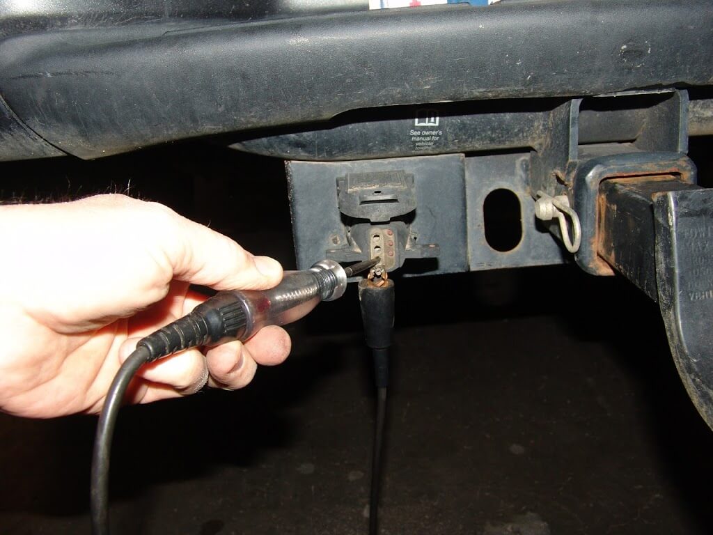
I located the fusible link that was attached to the same yellow wire that is located at the regulator connector and it was good as evidenced by the illuminated test light that is probing the yellow wire just past the actual fusible link. So I have an open circuit somewhere between here and the alternator.

Looking around I spotted the engine harness to main harness junction block just behind the throttle body area. There is a bolt with a 10 mm head that secures the two halves together.

After loosening the screw and tugging on the connectors the two halves came apart. I could see the problem once the connectors were separated but  I had to maneuver the connector up and around through the throttle cable area to be able to work on the repair.

I used a long screwdriver to release the latch that was securing the lower connector to a metal bracket. It is just like the ones used to secure the fuse box.

I then had to maneuver that connector and wiring up between the master cylinder and the throttle body cable bracket to have enough room to work with it.

I chose to make a two wire quick disconnect harness up to make the bypass of the burnt terminals. Also note that I used a sealer on the cut ends of the wires in the original connectors. This will prevent  fluids from entering into that connector through the open wire ends.

My male and female two wire connectors wired into both halves of the harnesses.

After putting the main harness connectors back into their original locations, I connected my installed bypass connectors.

I secured them with a wire tie to the original connector bodies.

A quick check and the regulator harness connector and power is now present on the yellow wire.

I started the engine and the alternator was now charging.

In the 1999 and later year models, Ford Motor Company redesigned how the alternators are controlled and the above tests are not relevant. The tests do apply to 1996, 1997 and 1998 year models with the 3.8 liter engines. The Windstars with the 3.0 liter engine have a similar alternator and tests but there is one extra wire that this one does not have. It is a white wire with a black stripe that connects between the center harness connector terminal and a single lead that plugs into the side of the alternator. One has to check to make sure that there is continuity between both ends of the white/black wire and confirm that the harnesses are connected to the alternator.