
This 2002 Ford F150 came in with the complaint that the driver’s window goes down but will not come back up. The driver’s door uses a one touch auto down feature that makes it a little difficult to test but this one was even more difficult due to the fact that the wiring diagrams did not match the truck. I had jumped the wiring at the window motor the evening before so the customer could drive home and bring it back when he had a ride.

The first thing I had to do in order to remove the door panel was the grasp the left edge trim panel and pull it from the door.

Once it was removed I had access to the hidden screw and I removed it.

Next I removed the switch panel by lifting up on the forward edge and sliding the assembly forward towards the door jamb.

After unhooking the harness connectors I grabbed the upper edge of the door handle bezel and pulled the forward edge away from the door.

With the front clip released I slid the bezel forward to release the rear edge.

The next step was to remove the screw that was behind the bezel

After that I grabbed the pull handle and lifted the door panel up and off of its hook retainers.

With the door panel away from the door I leaned it out and reached down and removed the courtesy light from the panel. Just twist and pull.

I removed the four screws that held the speaker in place.

Depressed the latch and pulled the harness connector from the speaker.

I started pulling the vapor barrier loose being careful not to damage it.

I then taped it up and out of the way so that I could work unencumbered.

After physically identifying the wires, I determined a test sequence. I did not take pictures of the testing until after I had put the door back together. So I had to pull the switch back loose to show testing. Testing was done with a fused jumper wire and a test light.First I checked the wires to see which one had power on it with the key on. It turned out to be a green wire at position 4 although the diagram shows that it should be a light blue/black wire.

Next I checked the brown/white wire, position 8 (white/black according to the diagram) as I had traced this one back to the motor when the door panel was off. It had power on it with the switch in the up position. I next connected my test light to a power source and checked to make sure it had a ground in the down position. It did.

I then by checking the diagram and by finding which wire position I need to test I found that the red/yellow wire, position 7 (tan/light blue according to diagram) was the next to test. I tested and found power in the down position but no ground signal in the up position. This was the cause of the complaint. A faulty switch.

To further prove my diagnosis I pushed the switch in the up position and jumped terminals 7 & 4 together with a fused jumper wire and the window went up. 100% power window switch fault.

I installed a new switch and called this one done.

2003 Ford Explorer Right Rear Turn Signal Inop

2003 Ford Explorer with the right rear turn signal inop. The right stoplight also was not working. Checked the bulb and socket in the rear and all checked okay except no power to right rear socket. As this is a common problem on Ford Explorer, Expeditions, Excursions, E Vans and F Trucks with tilt wheel I went to the steering column to inspect.
There are three screws that have to be removed from the lower steering column cover on this vehicle. Also the ignition lock cylinder may need to be removed. To do so turn the key on and with a small screwdriver or similar tool depress the retaining pin either through the access hole in the cover or remove the cover for easier pin location. Remove the tilt lever handle also.

With the lower cover removed, tilt the wheel fully down and remove the upper cover. On some models the instrument cluster trim panel will need to be removed.

Locate the broken or pulled out wires and terminals. Some vehicles only have the plastic locks broken in the connector and as a result the wires will pull out and create an open circuit. Whenever you come across this problem on these trucks, activate the offending switch (right turn signal on this vehicle) and tilt the wheel up and down to see if the circuit comes back. This is and easy, quick test to locate the problem.

This particular vehicle had broken wires. Only one shows in the picture but the other finished breaking during repairs. Normally there are only one or two wires that are giving a problem and in order to save time for the customer and produce a neater repair I transfer the good wiring from the old connector to the new one and only splice the damaged ones. Also if the locks in the plastic connector are broken the plastic connector itself has to be replaced. Sometimes there are no wire issues just broken plastic locks.

The final step before assembly is to form the new wires to lay in place so that they can freely move with the pivot of the tilt wheel and so that they do not touch any moving parts (shifter).

To order this repair harness please click here.
2003 Chrysler Town & Country Air Conditioning Compressor Does Not Come On

This 2003 Chrysler Town & Country Mini Van came in with the complaint that sometimes the air conditioning is not cold and sometimes it works fine. Seeing as how refrigerant charge normally will not cause this condition, I decided to run the vehicle with the a/c on and the controls set to full cold and low blower. This will force the compressor to be cycled on and off. I set the parking brake, chocked the wheel and left it running while I listened to the a/c clutch cycling. After about 20 minutes of cycling I could not hear any more changes. I went to investigate and sure enough the clutch was not turning. Being down this road before I looked at the odometer reading and it was 180,000 +. With that in mind I accessed the compressor clutch hub and pushed it in with an old broom handle, the clutch engaged and worked fine until it was time to cycle off again. It cycled off and would not come back on until I hit it with the broom handle.By the way I do not recommend my method to the average person as it can be dangerous. The preferred method is to access the a/c compressor and measure the clutch gap with a feeler gauge and compare it to the manufacturers specifications. Be sure to measure in at least three locations for an average reading.

The gap on this clutch was sitting at about .060″ and should have been around .015″ to .020″. The next step was to remove the center bolt. Most of the time you can hold the clutch hub with your hand and then use a ratchet and socket to remove the bolt.

Sometimes you will need a tool similar to the one shown below which is specifically made to hold compressor clutches. After the bolt is removed you will need to grab the hub ring and pull it off while slightly rocking the hub back and forth. DO NOT PRY ON THE CLUTCH HUB AS DAMAGE MAY OCCUR.

With the clutch hub removed you now need to remove all of the shims. Because of magnetism you will probably have to push them through from the front and garb them at the rear of the hub.

Calculate the amount of shims needed to be removed by subtracting the manufacturers specifications from the readings you took earlier. You may have to go to a parts store for a shim assortment to be able to properly shim the clutch to the right specs.

This is becoming a regular repair on a lot of vehicles because the vehicles and compressors are lasting longer than the clutch is designed to. My experience is that if the compressor sounds and tests good at the time of adjustment the owner can usually get another couple of years of use before something else goes wrong with the system.
2005 Chevrolet Malibu Turn Signals Inop

A 2005 Chevrolet Malibu came in with no outside turn signals working and the inside indicators
were flashing quickly. I know this sounds a little crazy but the first thing to check is codes. Codes B3948, B3949, B3950 and B3951 were stored for possible short to power. With all of these codes I was expecting to find a faulty body control computer but I decided to use old experience and realized that if the bulbs had a faulty ground then the body computer might interpret that condition as a short to power. Let’s check the basic first. I went to the right front light assembly and removed it in order to inspect the bulb wiring.

There are two 10 mm headed screws that hold the assembly in place.

After removing the two screws the light assembly can be lifted up and away from the car. Next I twisted the access cap off of the assembly.

This is what I found. A burnt socket.

And a melted bulb.

I replaced the socket assembly by cutting and splicing one wire at a time, making sure to stagger the joints. Replacement sockets are available by clicking here. Although this socket is only listed to replace the rear turn signal sockets, you can see that it also clearly fits the front application as well. If you know that it will fit other year models please leave that info in the comments below.

I heated the dual wall heat shrink tubing.

Installed the socket with a new bulb in the light assembly.

Tested the right turn signals and that light worked. One down three to go. I repeated the process for the left front light assembly and that light also started working. Now to the rear lights. I started at the left rear. First I removed the one phillips head screw.

Next I went inside the trunk and removed the cargo net retaining nut.

After moving the trim cover I could access the two plastic wing nuts that hold the light assembly in place.

After that the light just pulls out. The edge above where the phillips headed screw was had to be pulled loose from some sealer that was behind the plastic.

Next I removed the turn signal socket and found yet another burnt socket. This one only comes as a subharness assembly so I removed the old and installed the new. The subharness is currently only available at your local dealership, the part number is 15869348.

Reassembled and tested and now after replacing four faulty sockets and bulbs all of the lights were working. I cleared the coded and rechecked the system and no codes returned.
I think it is a little strange that the customer waited till all of the lights failed before bringing the car in for repair. The customer claimed that all of the turn signals stopped at the same time maybe, maybe not.
As for the cause, the front turn signal sockets also are used a daytime running lights and receive a lot of use which generates heat which causes the above problems. The rear turn signal sockets also are used as stoplights and depending on driving habits can also be used a lot. Not much you could do about the DRL but the stoplights would last much longer if the driver’s would let off of the brake pedal occasionally while stopped in lines or traffic and let the lights cool.
1996 Chevrolet 1500 Truck Ignition Switch

1996 Chevrolet 1500 Truck came in with an intermittent no run condition. When the no run condition would occur the dash warning lights would not come on either. After cycling the ignition switch several times the lights would come on and then the engine would crank and start. I checked basic battery and cables for loose connections and found none. I felt like this was an ignition switch condition, so I picked it as a starting place. In order to fully access the ignition switch and wiring some disassembly is required. Disable the airbag system and disconnect the battery according to manufacturers instructions.

The upper dash bezel and the lower dash knee bolster have to be removed.

To remove the upper dash bezel I grabbed the edge and pulled straight towards the seat. Then I repeated the process all the way around the bezel until it was fully released.

Next I had to remove the harness connectors from the bezel mounted switches. The headlight switch has a locking tab that has to be depressed.

There is a push button tab on the cargo light switch that has to be depressed before the harness can be removed. For some reason I find this switch particularly hard to release but perseverance wins in the end. Sometimes there are several switches at this location.
After I had released all of the harness connectors, I tilted the steering column fully down and moved the shifter to the drive one position. Then with a little bit of flexing I removed the bezel.

The next step was to disconnect the park brake release cable. I first pulled the release to make sure the parking brake was not set. It can be very painful if it was set and it released while removing the cable. I have been pinched and beat over the years by not remembering to do this, in fact I could not wear a ring for two years due jamming my finger one time. To remove the cable I next pulled the forward lever towards me so that I could remove the cable end. Next I used a screw driver to force the plastic cable housing from the park brake assembly. There is also a hold down clip that has to be removed or opened a little further up on the steel dash framework. I could not get the camera positioned for a picture however.

There are four 7 mm headed screws that have to be removed from the lower edge of the knee bolster. After that I pulled the panel towards the seat and removed it.

After the plastic panel was removed I had to remove the two steel panels. one is held on by two 7 mm headed screws and the other is held on by four 10 mm headed screws.

Next, I removed the heavy steel bar under the steering column, it is held on by four 15 mm nuts. This one and some extra wiring attached to it for a XM radio that I had to remove.

Next I located the ignition switch junction block at the left side of the steering column. It has a 7 mm headed screw in the middle of it.

With all of that removed I could now access the wiring for the ignition switch. I also decided to remove the lower steering column cover. There are two torx screws that have to be removed.

Next the tilt handle had to be removed. I grabbed it and pulled it straight out towards the driver’s door.

The lower cover has to be flexed and rolled so that the lip can be released from under the steering wheel and then pulled from the rear hinge pins. the correct procedure is to remove the steering wheel but I have taken hundreds of these apart using this procedure.

There are two screws that hold the upper cover in place. The left one can be seen slightly above center of the upper picture. The right one can be seen in the center of the lower picture just above the ignition switch.

For testing purposes I removed the plastic cover over the ignition switch wires and reconnected the battery. I checked power on both of the pink wires while switching the key on and off. The pink wire towards the front of the truck would not power up sometimes or it would have a delay. Time to change the switch.

After removing the two screws mentioned earlier, I could lift the upper cover to gain access to the lock cylinder release pin. The battery has to be disconnected before removing the lock cylinder because the cylinder has to be turned to the full crank position before the pin can be depressed. I use a hooked tool that is actually designed for loosening coolant hoses but a hanger can be cut and bent to do the same thing. Again with the key turned to the full crank condition, I depressed the pin and pulled the lock cylinder out.

The following picture shows the access hole for the lock cylinder pin.

There are two screws that hold the actual switch to the steering column and now I could finally get to them.

After removing the screws and sliding the switch out, I had to remove the key in switch from the steering column housing. It has a small clip that has to be depressed and then it has to be rotated and lifted out of place.

There are several wire ties and a piece of abrasion cloth that have to be removed from the wiring harnesses. The combination switch wiring has to be unclipped from the ignition switch terminal block that was shown earlier in this post. Make sure that all wire ties and the abrasion cloth are put back in place as they are there to prevent future shorts. Reverse the procedure to reassemble. Although this post is quite long the actual time is about thirty minutes after you have some experience. I would imagine a first timer would need about an hour depending on general experience level.
1992 Chevrolet Camaro Rear Hatch Does Not Close

This 1992 Chevrolet Camaro came in with the complaint of the rear hatch pull down motor runs continuously and it will not close the hatch. This post also applies to Pontiac Firebirds. The fuse had already been removed in order to keep the battery from going dead. On the rear trim panel there are two phillips headed screws that have to be removed. There are also two plastic screws at each end that need to be removed. As you can see from the pictures you really only have to pull one end loose.

After gaining access to the motor assembly you first need to mark the locations of the mounting bolts so that the assembly can be put back in the same location. The mounting screws are the adjustment for the rear hatch at closure. Draw a circle around each bolt with a marker in order to make reassembly easy.

There is also a cable assembly that has to be removed. It can be seen in the center of the picture above. There is a 8mm headed bolt holding it in place

After the assembly is out of the vehicle, you will need to remove the switch from the assembly.

It is retained by a 7mm headed screw.

After the switch is out of the way, you will need to remove three 11mm headed screws that hold the gear cover plate to the plastic housing. Then slide the center metal assembly from the plastic body.

The gear shown below had several teeth missing and was the cause of the motor running all of the time with no mechanism movement. Unscrew the gear from the main shaft and position all of the pieces aside.

Slide the motor assembly up and out of the plastic body.

Now clean up all grease and grime from the parts, making sure not to get any in the thrust bearing.With your cleanup done, place the thrust bearing on the shaft in the correct direction, screw on the new gear and place the thrust washer on the lower end of gear. Place new grease in assembly and reassemble.

Wipe the excess grease from the assembly and reinstall the switch. You are now ready to install it in the car.

2003 Ford F250 Super Duty Gauges Stopped Working And Fuse #44 Blows

A 2003 Ford F250 Super Duty came in with the complaint that when fuse #44 in the underdash fuse block blows the gauges stop working.

First I removed the lower dash cover, which is held in place by four quick release screws.

Then I removed the fuse block cover and confirmed that fuse #44 was indeed the correct fuse. It was.

After looking through fuse information and wiring diagrams I found that the overdrive switch was on this fuse circuit. I replaced the fuse, cranked the truck and moved the shifter handle from park to drive and back several times and as I had figured from previous experience the fuse blew. I removed the steering column covers by first removing the retaining screws and pull the lower cover off. I then removed the lock cylinder by switching the key on and pushing in the retaining pin at the bottom of the lock cylinder.

After the lock cylinder was out of the way I removed the upper cover to gain access to the overdrive switch wiring.

And there it is, a nice little short in the switch wiring. The wiring had a lot of damage to it and if you click on the picture to enlarge it you can see it better.

I decided to replace the lever assembly with switch and harness due to the degree of damage. If you caught this soon enough you could wrap it with tape and position it so that it will not happen again for a long while. To remove the lever assembly simply tap the pivot pin up from the underside and finish pulling it out with a pair of pliers. Pull the handle out of the shifter assembly, push the new one into position and install the pivot pin. Make sure that you fully seat the pin so that it will not work itself back out.

1998 Ford Windstar Power Mirrors Do Not Work In All Directions

This is a very common problem on most Ford, Lincoln and Mercury products with power mirrors. A vehicle will come in with a complaint of the power mirror does not work in one or two direction. The simplest test is to see if both mirrors react in the same manner. If they do I go with the odds that the switch is faulty because it is highly unlikely that both mirror assemblies would have the exact same problem. I also keep a test switch or two around to save time. Anyhow this is the procedure for changing the power mirror switch on a 1998 Ford Windstar.
The switch is obviously located on the driver’s switch panel.

You will first need to remove the interior door handle trim panel.

Using your fingers or a flat tool, lift the forward edge of the trim panel up.

After loosening the front edge continue around and remove the trim panel by pulling it forward past the door handle.

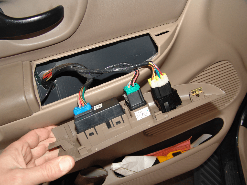
Next lift the front edge of the switch panel to release the spring clip. Then pull forward to finish releasing it from the door panel.

With the panel removed you will now be able to access the wiring harness connectors.

Unplug the power mirror switch harness connector by depressing the thumb latch and pull it from the switch.

Depress the locking tabs on the switch.

Push the switch through the panel and remove.

Simply reverse the procedure to reassemble.
2003 Chevrolet Impala Security Light Flashes and The Engine Will Not Run

This car has an intermittent no start condition with the security light flashing. Checked codes and found code B2960 stored. The code is for a valid but incorrect passkey signal. Now there are several different things that can cause this code but the most common is a failing passkey sensor which is part of the ignition tumbler kit. Some of the others are a faulty Ignition Switch, Body Control Computer and poor connections in the wiring harness. Because this problem is usually so intermittent there is not much real testing you can do that will result in a clear answer. I have found the only practical thing to do is to look at passkey voltage with a Tech 2 and gently wiggle the wiring some at the ignition switch and the BCM to see if there is any problem with the harness. Also look at passkey voltage while switching the key off and on. It should be about 5 volts when you initially switch the key on and then drop to a value higher than 0 and lower than 5 volts. Normally I see anywhere from .78 to 3.9 volts. If I see no other problems I always change the ignition tumbler kit and install a new ignition switch as well. If one is failing the other will not be far behind. I have seen plenty of these ignition switches fail without a passkey fault so I replace both as a rule.
With that out of the way this is the what you have to do to change the switch. Drop the tilt steering column to the full tilt down position. Remove both of the dash end caps and remove a screw from each end. Start pulling the trim panel from either end until the clips release. If it does not seem to want to release check for any extra screws that may be retaining the panel. If none are found pull harder but please be careful as panels can break.

After the trim panel is released you will have to disconnect the switches. The hazard switch needs the center tab depressed while you pull the harness connector from the switch.

The Traction control switch needs the center tab lifted slightly while the harness connector is pulled from the switch.

You will also need to remove the lower panels. There and a coulpe of retaining screws and a retaining pin or two. After all retainers are removed pull the cover towards the driver’s seat.

Disconnect the trunk release switch if present and now you will find a metal panel.

Remove the attaching screws and place aside.

Next you will need to remove the two 10mm headed screws that hold the switch assembly to the dash.

Next pull the switch down through the opening in the bottom of the dash.

With the key off release the locking tabs and pull the two main harnesses from the ignition switch. Make sure the key is off, it will save programming time.

Next turn the key on and depress the locking tab for the shifter interlock cable and pull the cable out of the switch.


Next depress the metal locking pin that hold the tumbler and sensor assembly into the ignition switch, rotate the key and pull the assembly out of the ignition switch.

Disconnect the sensor wiring harness by depressing the two side locking tabs and pull from the switch.

Install the new ignition switch and then install the new tumbler and sensor assembly.
I have another post for assembly of the tumbler kit. Please click here to see that post.

After the ignition switch and tumbler assembly are back together turn the key on and reinstall the shifter interlock cable. Then Make Sure The Key Is Off and Then Connect The Two Main Harness Connectors. Again this saves programming or relearn time. Now attempt to start the engine. Do Not be surprised if it does not start. Leave The Key ON and Wait about ten minutes or until the security light stops flashing. You may have to repeat this process up to four times in all before the system will relearn the new sensor value. The closer the new sensor value is to the original the quicker it will relearn. On some rare occasions you will have to use a Tech 2 and reprogramming software to teach the system the new value.
2003 Chevrolet Impala Ignition Lock Cylinder Replacement

This post is for replacing an ignition key tumbler kit in a 2003 Chevrolet Impala but it applies to most General Motor Vehicles from the late 1990’s to 2007
With a small screwdriver depress the retaining pin, rotate and pull the tumbler assembly from the sensor housing.

The retaining pin can be seen in the picture below. It is the angle piece pointing down. Before further disassembly place your thumb on the locking bar and take the key in and out of the tumbler assembly so that you can get a feel for how the locking bar should drop into position when the key is inserted. This is helpful to know later when assembling the new tumbler

The retaining bar will have to be removed.

Use a small screwdriver to pry it out of the housing.

After the bar is removed, take all of the springs out.

Next take a pick and lift out one tumbler at a time.

Make yourself a chart so that you can write down the numbers that are on the individual tumblers and keep track of their positions in the tumbler housing. This is your key code. You can get this code from your dealer if you need to but you will have to show a photo id and proof of vehicle ownership.

The original tumblers are brass colored and the replacements are silver colored. There are numbers stamped on each one and they range from 1-4

In particular, if you have never done this before and do not have any spare parts, make sure that the package is unopened. This will save you a lot of grief.

Install the new tumblers in the proper order and check with the key to make sure that the locking bar drops in evenly when the key is fully inserted and the tumblers are pushed in to make contact with the key.

If the bar does not drop in evenly you have either assembled incorrectly or your key is worn out.

Remove the key and push all of the tumblers fully in, light pressure with a small screwdriver or pick is all that is needed. With the tumblers pushed in, place the new springs into position

Install the new retaining bar.

Install the new spring and angled retainer. Not shown but it should go in the square hole that is pointing down at the right hand side of the tumbler housing.

Insert supplied grease into the tumbler assembly and install in the new sensor housing.

There are detailed instructions that come with the kit you should read and fully understand before actually attempting this repair. The information I am providing is meant to be an aide to the factory instructions.