
This 1997 Nissan Maxima was towed in from another shop after unsuccessful repair attempts. I am not sure how many shops it has been to. Tried to crank vehicle, it spit and coughed and jumped and carried on but I managed to get it to fire a little by depessing the gas pedal to the floor {clear flood mode}.
I checked the plugs and they were black and fouled out and several showed signs of gas blowby at the insulator seal, so I installed a new set of plugs. cranked the engine and it ran. After a couple of minutes it had cleared up and was running good. Ran a few more minutes for good measure. Turned engine off and recranked. It cranked and ran fine. Did the other shops miss something this simple? I don’t know? Cranked it several times and no problems, time for a test drive. Backed the car out of the shop and took off on a test drive. Right, got 20 feet and it stalled and would not crank back up. Kind of figured it, plugs would be too easy.
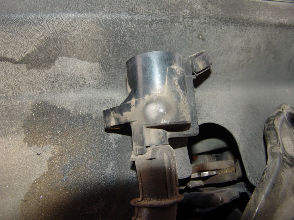
Got the scanner out and checked codes P0325 and P0340 were stored. The P0325 code is for a knock sensor and will not cause the engine to not run, so I was going to concentrate on the P0340 code. The code P0340 is for a cam sensor error. Checked the cam sensor and it had been replaced.

I needed to check the continuity of the wires between the cam sensor and the ECM. The ECM is located under the center of the dash as shown below.
I removed the white plastic cover to have better access to the wiring.

I had to use an ohm meter hooked to both ends of the two wires. While the harness (shown below) was wiggled. Sure enough one of the two wires was broken. In doing this repair I had to try several things before I came up with a way to repair this vehicle in a cost effective way. The harness costs about two thousand dollars plus installation.

I clipped the two wires near the ECM harness connector. Then started to look for a way to run new wires. My first choice would be to attach new wires to the old, with splicing connectors and pull them through the harness, then splice at the other end. This would not work as the wires are glued into the grommet at the firewall. It would be virtually impossible for me to identify the two wires at the ECM so you will need to access that information from Mitchell 1. There is a link at the top right of this page.

My next choice was to try and run the new wires through, hopefully another grommet. The problem is the only other thing I could see was the a/c drain tube. Running new wires there did not seem like a good idea. To get a really good look the evaporator case needed to come out. Recovered the refrigerant and removed all of the interior mounting screws.


Problem, the evaporator case will not come out past the glove box support brace. A very close look and I determined that if I removed the metal brace. Then cut the plastic between the two screw holes on each side that the evaporator case would come out. When reassembling the two screws would hold the plastic pieces together. It appears to me that an engineer actually designed it to be cut, if the evaporator case needed to be removed.

The cut on the right side of the glove box opening.

At least now I can see where the wires go through the firewall. I felt around and decided that I could go through the original grommet. On the lower right side, as it is viewed in the pictures below.

I have a special tool for doing this procedure. The tool is similar to a screwdriver but it has hole running through it. Using the sharp end I pierced the grommet and ran the wire through the hole in the tool.

With the wire run through the hole in the tool and to the other side of the firewall, I pulled the tool back out over the remaining wire on the inside of the vehicle.


A close up look at the hole in the handle.

The sharp end of the tool that easily pierces the rubber grommet.

I purchased a special piece of shielded, twisted, pair wire cable from an aircraft supplier. The first thing that had to be done was to loosen the shielding and move it down the cable assembly enough to stagger the joints. I did have to split it length way also.

After prepping the cable, I connected it to the factory harness connector. I staggered the joints.

Heated the tubing and shrank it into place.

Twisted the remaining cable, around the repair.

Pulled the shielding back up and around the spliced wires, then used tape to hold it in place.

I repeated the process at the other end near the computer. I then taped and wire tied the new cable to the old harness. One thing that I learned through this whole experience is that if at all possible do not pull the harness out from under the dash. It is looped to the top of the ECM and is almost impossible to get it back into place. The reason I had pulled it out was so that I could pull the new wiring through the old harness and just attach it on both ends. The glue in the fire wall grommet prevented me from doing this, so in the end, there was no reason to pull the harness loose that far.

A closer look at where the wiring breaks inside the harness. My experience on this one also convinced me to not open the harness to actually see the damage. Way too hard to get it all back together that way. Just make sure the wiring is the problem with a meter and/or piggy back a new harness to the outside of the old harness and attach it at both ends.


