2007 Suzuki Grand Vitara, No Low Beam Headlights

This 2007 Suzuki Grand Vitara came in with the complaint of no low beam headlights. I checked the wiring at the passenger side low beam head light first and this is what I found. A burnt harness connector and bulb adapter.

I wired in a new harness connector. I had some NOS (New Old Stock) two wire connectors in my shop, so I used those, to get rid of them. Notice that the original connector had three cavities. The replacements will as well. The third wire in the perpendicular position can easily be removed with a pocket screwdriver. Locate the locking tab on the terminal end of the connector. Insert the screwdriver blade into the slot (notched), depress the locking tab and pull the wire from the connector body. You now have a connector similar to the original. Three slots and two wires. if you do not feel comfortable removing the terminal and wire, you can simply tape off the extra wire end.

To order a repair kit that includes; 4169  harness,  34175-33E50 adapter and  Flösser®  H7 bulb (high quality 55W bulb made in Germany), please click here.

Installed a new bulb onto a new adapter. Yes, it is fully assembled. I think an engineer really goofed this one up. There is not enough contact area between the bulb terminals and the adapter terminals. Also keep in mind that at no time should anything touch the glass on the new bulb. Even the oil from your finger print will damage the bulb. What happens is the oil or any other substance causes uneven heating of the glass when the light is turned on. The glass may shatter or at least crack. this will result in the loss of the inert gas that protects the bulb element and it will quickly burn out. Never power up one of these bulbs outside of it’s housing assembly. You could be hurt by shattering glass or badly burnt.

Placed the bulb and bulb adapter into the rear of the light assembly and secured using the wire hinge lock.

Installed the rubber boot for the assembly. The boot seals on the outer housing and it also seals on the bulb adapter.

Then connected the new harness to the two terminal bulb adapter.

Notice, that I back filled the harness connector with white lithium grease. I repeated the process on the driver’s side and this car was fixed.

2004 Chevrolet Trailblazer, Identifying Heater A/C Actuators

This 2004 Chevrolet Trailblazer came in with the air flow stuck coming out of the defroster. I have already done a post on how to replace the faulty mode actuator, but I did not have a good enough picture to identify all of the actuators on the driver’s side of the dash. To see that post please click here. The view below shows the three actuators and is taken from the perspective of the driver’s feet, looking above the accelerator pedal and towards the center of the dash.

If you click on the picture it will enlarge to show more detail. This layout generally applies to 2003, 2004, 2005 2006, 2007, 2008 and 2009 Chevrolet Trailblazer and GMC Envoy.  It also applies to Buick Rainier, Isuzu Ascender, Oldsmobile Bravada, Saab 9-7X and Chevy SSR. This second group of vehicles, of course did not exist, during all years between 2003-2009.

Once the mode actuator is removed and the new one is ready to be installed, you will need to locate the indexing pin as shown in the picture below. That pin slides into the notch on the white gear on the actuator.

I slide the new actuator into place with the notch and pin aligned and then rotate the actuator slightly to align the mounting holes.

The actuator on the right is the new actuator and the indexing slot is clearly marked. Please click on the picture to enlarge for a better view. The picture also shows the over traveled (stuck) position of the old actuator.

If you would like to purchase the Mode Valve Actuator (part # 15-73596), you can do so by clicking here.

1998 Chevrolet C1500, Changing The Blower Motor

This 1998 Chevrolet C1500 came in with a no blower complaint. The starting place for testing is at the blower motor. The blower motor is located behind the passenger side of the dash and is accessed by removing the glove box.

After opening the glove box there are two retainers that have to be dealt with.  The one on the left is a plastic cable. To release it, lift the locking tab, lift the door slightly and pull the cable towards you.

The second retainer is a bump stop and to release it, flex the glove box housing inward as shown below.

After both retainers are released, lower the glove box down and rotate it off of its hinge pins.

Locate the purple wire at the blower motor, switch the ignition on and set the blower switch to the high position. I had power (red glow at my finger tips) which told me that the basic controls were working on the power side.

Next I checked for power on the black ground wire. That’s right, I checked for power on the ground wire. If I would have seen power on the black wire it would indicate that the power coming in on the purple wire was going all of the way through the motor windings and brushes and that there was no ground being supplied to the black wire.

To further confirm that the ground was okay, I placed a jumper wire into the purple wire, connected my test light clamp to the jumper wire. Then, I touched the black wire and my test light lit up indicating that both power and ground are present. With the wires reconnected to the blower motor, I bumped the back of the blower motor with the palm of may hand. This will sometimes reset worn brushes in a faulty blower motor to further confirm the test results.

To remove the cover over the blower motor the wires of course have to be disconnected. Then you have to release the upper and lower retainers. At the top, the cover has a slot in it that hooks over a flat pin. Lift up on the rear edge and lift the cover off of the flat pin.

At the bottom there is a round pin and there is a stepped notch in the cover. You have to push the cover towards the firewall and then pull the cover off of the lower pin.

After both retainers are released, the cover can be pulled down in stages as you flex it and move it around. It will catch in different places.

Finally you can see the blower motor.

The lower screws are easy to remove. The two upper screws are a little more difficult and you will need a swivel to remove them.

Once the screws are out the blower motor will come out. Pull it out until it it full loose of then housing then rotate the motor until the flat edge is pointing up. Roll the motor down and out. The fan blade will need to be flexed also.

The new motor on the left and the old on on the right.

The new motor does not come with the ground terminal attached, so the old one has to be removed and attached to the new motor. Note the position of the terminal.

Now, the paint has to be removed from the new motor where the ground terminal attaches. A pocket knife works well for this. Install the ground terminal in the same position as it was in on the old motor. If you do not the cover will not line up correctly. Tighten the attaching screw. Do not over tighten and strip the metal out. Do not leave loose as heat will build up and burn the terminal.

The new motor also does not come withe the mounting ferrules or  tubes either, so they also need to be transferred.

The fan blade or impeller has to be flexed slightly to place the motor back into the housing. The motor can only be installed one way that will allow the vent tube to be properly attached. I actually prefer using the old vent hose if it is in good shape. It makes the cover installation easier.

It is aggravating, but to put the cover back into place, it will have to be worked on in stages

I had noticed that my jumper wire was a little loose in the terminal on the purple wire so I tightened the spring tension of the terminal as shown below.

If I would have had no power at the purple wire I would have gone to the blower relay and resistor at the left side of the glove box opening to do more testing.

To see more testing related to the relay and resistor please click here.

1997 Infiniti Q45 Changing The Alternator & Harness Connector

This 1997 Infiniti Q45 Came in with a battery going dead condition. I diagnosed it as a faulty alternator. I also found that during the alternator replacement that the regulator harness connector or pigtail needed to be replaced.

Replacing this alternator looks like it would be quite difficult but it really is fairly easy. The only thing that really slows the process down is having to drain some of the coolant from the engine. To do this repair, start by making sure you know the anti-theft code for the radio (if your radio has this feature and it is active) and then disconnect the battery.

The first thing to do was to drain the coolant level down. Starting with removing the cap.

The drain screw in the bottom of the radiator requires a #3 Phillips head screw driver to remove it. There probably is enough room to use a flat  blade or common screw driver. Just be careful to not damage the plastic screw. I do not like that the bottom covers are missing from this car. Notice the rusty screws on the lower radiator support. There should have been a panel there.

The coolant does not have to be fully drained. Let it drain until there is no more coolant in the cap opening and then for good measure another cup or so of coolant.

Next remove the air intake duct that runs across the top of the radiator.

With that out of the way, you can start to see the alternator a little better. There are two 10 mm headed bolts that hold the steel plate (belt shield) to the aluminum coolant housing. There are two more 10 mm bolts that hold the coolant housing to the engine. Remove these as well.

Now, two 12 mm bolts that hold the steel plate to the intake. Also two 10 mm bolts that hold the wiring harnesses in place.

Loosen and remove the top alternator mounting bolt. Then remove the steel bracket.

Loosen the nut in the center of the tensioner pulley assembly. Then loosen the adjustment bolt until the belt is loose enough to pull it from the alternator.

Loosen and remove the alternator lower bolt.

Remove the nut on the alternator output stud and disconnect the wiring harness.

Loosen the far right hand hose clamp as shown in the pictures and position the hose and housing assembly out of the way. Unclip the harness hold down above the exposed pipe in the picture below. Rock the alternator back, forth and up until the alternator is free of the blower mounting bracket. Then roll the alternator forward and out of the hole.

Reverse the procedure to install the new alternator. You will need a magnet on a stick or similar devise to hold the lower nut until it is started on the lower alternator mounting bolt.

Make sure you tighten the bolt slowly and that the nut is being held squarely or it may cross thread.

The plastic was very brittle at the regulator harness connector and the wires pulled out. I had to install a new connector to finish the job.

Rather than cut and splice the wires, I chose to remove all of the wiring from the new connector and secure the old terminals  into the new connector body. If you need one of these connectors please click here.

Finish by reassembling in the reverse order. Make sure the drain screw is closed and refill the cooling system.

1999 Lexus ES 300, Code P0171 Stored

This 1999 Lexus ES300  came in with the service engine soon light on. I did a quick code check and found code P0171 stored. Fuel system lean bank one. I believe in checking simple things first and the Mass Air Flow sensor is very easy to access and remove. One plug and two screws.

Pull it out and look into the holes in the under side.

There was dirt build up (fuzz) on the sensor elements. A light and very gentle scraping with a small screwdriver and the elements were clean again. The elements are deep in the sensor and you can barely see them in the picture below. They are the two gray, horizontal lines, deep in the recess.

Cleared the code and checked the fuel trims and all was well. I like something easy for a change.

2002 Cadillac Deville, B0248 B0249, No A/C Mode Control

This 2002 Cadillac Deville came in with the complaint that the customer could not control  the air flow modes.  The control panel showed movement but the air flow was stuck on vent and the air flow was not very strong. A quick visual check of the mode actuator found that someone had unplugged it so that it would stay in one position. I plugged it back up and did some checking and determined the problem was indeed a faulty mode actuator assembly.

This repair should begin with the use of a Tech-2 or similar scan tool to properly diagnose the problem. Not many people have these tools at their disposal so here’s a trick to check it without a scan tool. You will of course have to get under the dash and have all wiring connected to do this. It is just easier to show how to use a quarter on a table. Place a quarter into the two slots in the shaft. Turn the key on and try to adjust the mode position in both directions. You should feel the shaft try to turn in at least one direction. If or when it stops before reaching its commanded position, use the quarter to rotate the shaft. If helping the actuator get past a sticking point is successful and the actuator comes to rest in its commanded position, you will have diagnosed an internal problem in the actuator. Again, this has to be done under the dash of course.

Now, once you have diagnosed a faulty mode actuator the fun begins. There are three ways to do this repair. The factory method involves removing the complete dash assembly. The second way is to remove the actuator from the mounting bracket and separate the cam gear from the actuator using a pry bar of some sort. I have never done it this way as it requires doing the same thing to the replacement part. It will void the warranty and you could wind up with two broken assemblies. Just my opinion. The third is the procedure I outline below.

Remove the lower dash cover and the vent duct. Sorry, no pictures of that. The next step is to remove the trim for the a/c controls and the radio. Unsnap it along the lower edge and the sides, then lift the bottom up and slid the two upper tabs out from under the wood grain trim panel.

There is a latch on either side of the radio that has to be released so that the radio can be removed. Do not disconnect the wiring for the radio unless you have the theft lock code. Carefully position the radio so it will hang without damaging the soft dash panels. Place a rag in between if needed.

With the radio out of the way, remove the 7 mm headed screw that is in the center of the picture below. Removing that screw will allow the duct to drop down enough so that you will  be able to work more comfortably.

The radio is hanging, the screw for the duct work is removed and now you have to get under the dash. You have to lay as I am shown in the picture below. Depending on coordination level you may also have to be in the same relative position, only face down. Now the most important step. Connect and turn on a battery charger. Switch the ignition on. Turn the blower on high and if at all possible position the actuator to the vent position. Doing this will keep the doors in the proper position for installing a new actuator.

A 1/4″ palm ratchet and long 5.5 mm socket are my tools of choice. It can be done with a regular ratchet also.

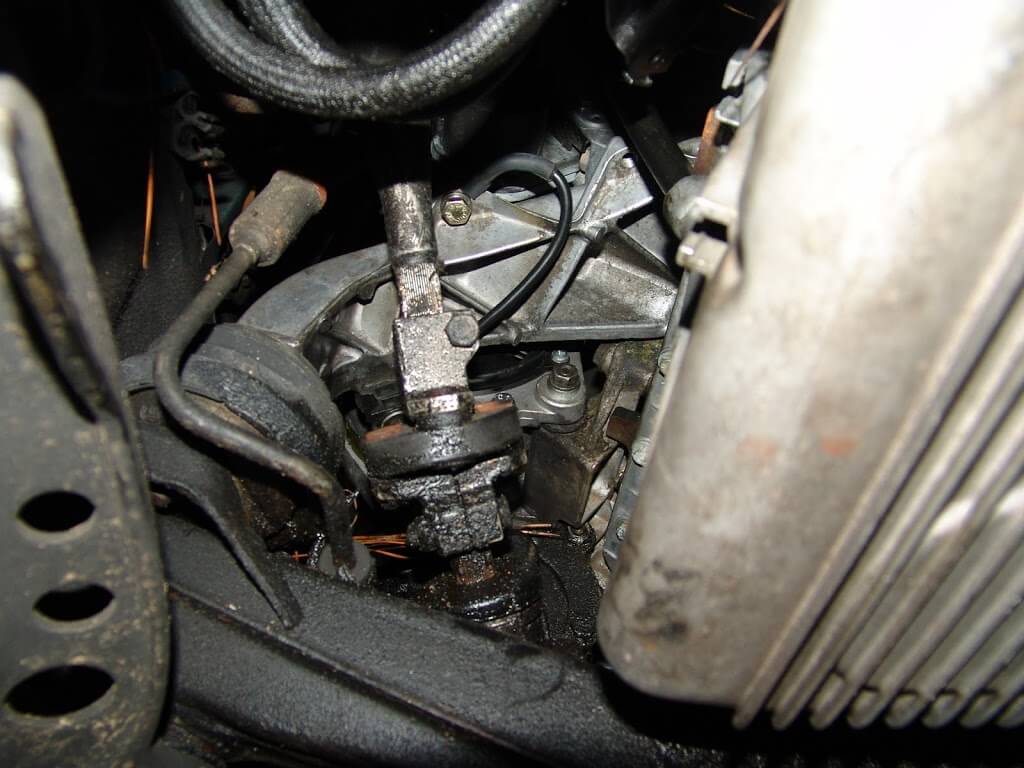
You will need to go up and over the duct work that is shown in the picture below.

Some one had already worked on this one and the duct was split just below my wrist in the pictures below.

Unplug the harness connector and remove the mounting screws from the actuator assembly.

With all screws removed and the harness unplugged, gently pull the actuator assembly towards the steering column. Once it is free of the a/c box continue to maneuver it until you can pull it down and out of the dash.

Although the following picture is slightly blurry, I am using it to show the relative position of the levers in relation to the duct work that I am pulling down.

Both the picture above and below should be rotated 90 degrees counter clockwise for the proper orientation. All three of the white levers in the picture will fall off, if they are moved around too much. I they do fall off just put them back on as shown in the picture below. To double check the lever positions,  all three of the male pegs should be as close together as possible.

The underside of the new actuator assembly.

The actuator may not be set properly when you get it, at least for this procedure. Pull the harness connector down and connect it to the actuator. Turn the key on and adjust the mode position on the a/c control head to the vent position. When the actuator stops, disconnect the wring from the actuator and turn the ignition off.

Maneuver the actuator back up into position and align the three pegs into the actuator cam gear. If all three do not drop into place do not be alarmed. Make sure that the lower one and the one closest to the firewall are in place. Put in a couple of screws but do not tighten them. Just snug them enough to hold the cam on the two pegs mentioned earlier.

Go around to the radio opening and use a long skinny screwdriver to align the last peg into the cam slots.

Leave the screwdriver in as a wedge and finish installing and tightening all of the screws.

To calibrate the actuator without a scan tool, remove the 15 amp IGN SW fuse in the rear under seat fuse box, position 29 (you can also disconnect the battery but memory settings will be lost). Remove the fuse for at least 60 seconds. Install the fuse and start the engine. Do not touch the a/c controls. Let the system run for about 4 minutes. Switch the ignition off for at least 10 seconds. Restart the engine and confirm the repair. To purchase this actuator please click here.

If you cannot flex backwards over the door sill and seat area, while resting your head between the brake and gas pedals, you cannot do this repair.

One more trick to make this job a little easier on the body.  It is not very stylish but it does help protect the underside of your wrist when going over the floor duct work.

1994 Toyota Pickup, EFI FuseBlows

This 1994 Toyota pickup came in with the complaint that the EFI fuse blows. The problem was intermittent at first but now the customer says that it happens so often that he is scared to drive it. The EFI fuse is located in the underhood fuse relay box.

The fuse was blown and would blow as soon at the key was turned on.

I have seen shorts in a few locations on these trucks over the years.

One of the more common locations is at the underhood diagnostic connector wiring. Sometimes the harness will rub the inner fender panel where it breaks out of main assembly. Not so in this case. The truck has been lifted and the harness has been moved. The place that would short out is now on top of a piece of plastic and insulated.

The next place to look is under the vehicle at the exhaust and drive shaft areas.

This looks like the short.

The wires are loose and slightly damaged here as well.

The oxygen sensor wires were where the short actually was though.

A closer look.

The short was limited to one wire, so I cut it and spliced it back together and sealed it with some heat shrink tubing.

Then put all of the wires back into the protective sleeve.

Added some split loom to further protect it.

Routed the wiring away from the exhaust and the driveshaft areas.

Then found a spot on the side of the transmission to secure then wiring harnesses.

1993 BMW 318IS, No Charge Condition

This 1993 BMW 318IS came in with the complaint that the battery would go dead after a few days of driving. The battery and the alternator had been changed, with no success. The first thing I spotted when I opened the hood and look at the alternator was a 12 gauge red ground wire,  that has been quite hot. European manfacturers generally use brown wire for primary ground circuits. I suspect a local American, with very little electrical knowledge, has been in here.

The wire color does not really matter that much but the size of the wire and the type of termination does.

The other end was connected to a small bolt on the side of the intake.

Now, for a little BMW charging system 101. BMW historically mounts their alternators using rubber bushings to prevent vibrations (keeps them quiet and smooth). This requires the alternators to have a ground wire between the alternator and chassis ground. The alternator on this vehicle is somewhere between 90 and 120 amps. The ground wire has to be adequate in size to carry the full output of the alternator. This red wire shown below,  would have never handled that much current and obviously did not.

To get a better look at the alternator, I put the vehicle in the air and looked at the alternator from the underside. If you look at the center of the picture below, you should see the empty hole were the ground wire should have been attached.

I made up an 8 gauge ground wire with heavy ring terminals and heat shrink tubing. Then, I attached one end, to the alternator ground.

The other end attached to the aluminum bracket, shown below. I was concerned about the wire being damaged by the steering shaft at some point, so I did a couple of things to prevent that from happening.  First of all the wire is heavy enough that it would be unlikely to fall onto the steering shaft. Next, there is a plastic bracket that you cannot see in the picture that I routed the wire into for support. I controlled the length of the wire also, to eliminate any excess.

The charging system is back working as designed. It turns out that engine in this vehicle has recently been changed and there a quite a few issues that were left unattended. I recommended that the customer take it back to the installer to finish the job.

1995 Mitsubishi Eclipse, Shade Tree, DIYer Disaster

This 1995 Mitsubishi Eclipse came in with a complaint that the 30 amp engine fuse would blow.  The customer stated that a friend of his that claimed to work on cars put a transmission in for him. Now there was smoke coming from the engine compartment and the 30 amp engine fuse in the underhood fuse box would blow. I racked the car up and looked at it from the underside. What was this guy thinking? I was surprised that it had not caught on fire.  Both of the inner cv joint boots were torn and it looked like they were recently ripped by hand and not from normal wear. Also most of the time the outer boots are the ones that split open. One of them had the clamp missing.

There was a substantial amount of transmission fluid leaking as evidenced from the red beads of fluid.

Transmission fluid and cv axle grease on the exhaust. Wonder why it is smoking under the hood?

Fluid on the catalytic converter.

Lower mount with the wrong bolt and nut. Not even tight.

Oh boy, all kinds of extra wire wrapped up in tape.

Cooling fan not bolted down properly.

If the car will run any length of time the radiator will have a hole or two worn into it.

I was wondering why the power steering was stiff? Worn out belt just hanging around.

All of the splash panels and inner fender panels are missing.

To me this has to be the most ridiculous part of the work that had been done on this car. More money and time were wasted on installing the wrong battery for this car than ever could have been spent to install the correct battery. You gotta love the greasy rag, as a positive battery post insulator. Let’s see, a fragile, combustible material between two metal objects, that create heat and sparks if they touch. I am not much of a cook but I know that is a recipe for disaster.

Don’t you like the way that the radiator hose it touching the exhaust heat shield?

Aluminum fence wire holding a harness connection together.

Sorry, I stuck a fuse in it and told the customer good luck with this. No diagnosis, No repair for the 30 amp engine fuse short.

I still cannot believe the battery installation.  Do not become this guy.  If you look under a hood and see anything like this, find out who did it and stay far, far away.

2002 Chevrolet Trailblazer, Poor Heat, Clicking Sound Under Dash

This 2002 Chevrolet Trailblazer came in with a clicking sound under the driver’s side of the dash and erratic control of heat and a/c, hot and cold,  air from the driver’s side of the dash. To find the actual site of the clicking noise, I had to remove some of the underside of the dash. Two screws up top.

Two screws under the bottom for the black hush panel.

Drop the hush panel down and unclip/ unbolt all of the stuff attached to it.

Remove the two screws at the lower edge of the knee panel. Lower and remove the knee panel.

Remove the four 10 mm nuts that hold the inner aluminum panel.

Remove the aluminum panel.

The driver floor vent duct needs to be removed. The left end of the duct has a retaining clip in it,  that holds the duct in place. You have to either remove the clip or firmly pull down on the left side of the duct and wiggle it until it comes loose.

Remove the hold down screws for the actuator through the openings in and around the bracket, 5.5 mm.

Remove the two 10 mm nuts and the wiring harness clamp from the studs as shown below.

Remove the 10 mm bolt from the leading edge of the bracket.

Now go back and loosen the studs as shown. You will need a torx socket for this operation.

With the two studs loosened from the inner aluminum bracket, grab the sheet metal bracket and pull it towards the steering column. This will allow enough room for the actuator to come out.

The new actuator did not come in the same position as the old when it was removed.  You can purchase a new actuator by clicking here.

The old actuator had a part number 16164972 and the new actuator has a label with part number 52402599.

I connected it to the wiring and turned the key on until it matched. I turned the key off as soon as it was in the correct position so that the actuator would not over travel and possibly get stuck.

I do not remember at this time if I left the wiring attached or disconnected it before reinstalling it in the dash. The sheet metal bracket has to be pulled again to get the actuator back into position. Then take your time and push the bracket back into place and align the two studs into the aluminum bracket, so that they will not cross thread.