2003 Chevrolet Silverado, Blower Does Not Work On Any Speed

This 2003 Chevrolet Silverado came in with the complaint that the blower did not work on any speed. The ABS and Brake lights were on as well.

Testing begins at the HVAC fuses in the driver’s side fuse box that is located behind the dash end cap.

The fuses need to be checked with the ignition switch on. The 10 amp fuse is listed as HVAC 1. The 30 amp fuse is listed as HTR A/C.  There was no power on either fuse.

Time to go to the ignition switch for more testing. Although you can jump to just separating the steering column cover. I find it much easier to remove the instrument cluster trim panel first.

Then the knee bolster or under dash cover.

Next a well placed screw driver and a little twisting and the tilt lever pops out.

The lower cover is now removed and I am checking for power on the orange wire. I was not expecting power here. Since there is power on the orange wire with the ignition on, the ignition switch is not the problem. This is why it pays to test before replacing parts. If there would have been no power at the orange wire with the ignition on and the engine cranked and ran normally, then the ignition switch would have been faulty.

It took a little bit of searching to find where the orange wire enters the rear of the driver’s side fuse box. I had to move the rest of the wires around to find the orange wire.

It was a little bit more difficult because the wire color had changed to brown. That made it slightly more difficult to find. The color change however was a clear indicator of heat damage.

The damaged wire and terminal are located in the top left in the picture below.

There is a blue secondary locking pin that had to be removed before the terminal could be properly removed. I used a small pocket screwdriver to remove the secondary lock.

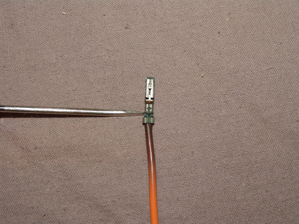
Another tool to lift the locking tab from the terminal.

The orange wire removed from the connector body.

Before cutting the wire I moved back to where the wire color was consistently orange. I did this so that I would be clear of any heat damage to the wire or insulation.

I made up a new wire and terminal and crimped it into place. I used heat shrink tubing to insulate the connection.

I installed the wire back into the connector body and secured it with the blue secondary locking tab.

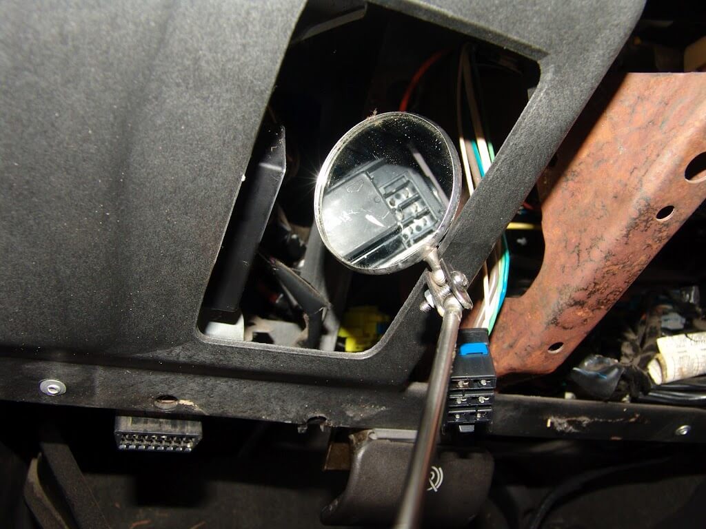
I used a mirror and flashlight to inspect the rear of the fuse box for damage. I could see signs of some melted plastic.

I loosened the 7 mm headed bolt that attaches the main harness to the rear of the fuse box.

There are a couple of latches that have to be released to remove the fuse box from it’s mounting bracket. You can see one of the latches above my thumb in the next picture.

With the fuse box fully removed form the truck I could inspect the terminals for damage. The damage to the fuse box was very minor and since one was not readily available, the customer and I decided to clean the terminal and reuse the fuse box.

To clean the terminal, I cut a slice off of an eraser and checked to make sure it would fit in between the terminals.

I then used my pocket screwdriver to support the eraser while I cleaned the terminal.

After installing the fuse box and repairing the harness, power is present at the fuses and the blower is back working.

A close examination of the damaged terminal and wires showed that the heat radiated out from the crimp. The terminal where it contacts the fuse box terminal was only very slightly heated.

The terminal where it contacts the fuse box terminal was only very slightly heated. This is why the fuse box was reused without any problem. If the center of the heat had been at the actual contact points between the male and female terminals, a new fuse box would have been needed to properly repair the condition.

This is a new wrinkle in ongoing blower failures on these trucks.

For more of the common problems with the HVAC systems on GM trucks click here.

2009 Mercury Grand Maquis, Air Will Not Blow Out Of Face Vents

This 2009 Mercury Grand Marquis came in with the complaint the air conditioner would only blow air through the defroster vents. Rarely would air come out of the face vents. This is a common problem and can be expensive to repair. A work around, of sorts, is to manually drop the blower speed to the lowest speed setting. Then switch the mode control to the Max A/C position. Slowly bring the blower speed up and note the speed setting when the air shifts from the face vents to the defrost position. Start over again and stop increasing the speed one position lower than when it switch to the defrost position earlier.

To do some testing, the a/c control head will need to be removed from the dash. This will allow access to  the vacuum lines at the rear of the unit. Remove the two 10 mm nuts and pull the hose connector from the a/c control assembly.

You can allow the control assembly to hang down while you check the vacuum system. Care should be taken not to damage the wiring, control assembly or dash surfaces.

Using a vacuum gauge connected to the black vacuum hose, check the vacuum signal with the engine running.

There are a couple of ways to test the vacuum actuators. One way is with a short piece of rigid vacuum tubing.

It can be used much as a jumper wire would be used to test a wiring circuit. Connecting the black vacuum supply hose to the blue panel door hose should produce air from the face vents. The engine  has to be running and the a/c switched on of course.

The other way to test is to use a hand vacuum pump and manually pump the air out of each line. This will check to see if the corresponding actuator reacts and if there are any leaks. All of the actuators reacted correctly and there were no leaks. The rest of the control assembly was working correctly, so the diagnosis was a faulty control head assembly.

The customer elected to have a new a/c control head assembly installed.

Since I neglected to take pictures of removing the old control head, I thought I would show how it is installed/removed at the end of this repair. Four 7 mm headed screws hold the control assembly in place.

To access the screws the trim panel first needs to be removed.

Using a wide bladed tool similar to what I am using in the pictures below, slide the tool under the panel in the two positions shown. Pry the panel away from the dash to release the spring clips.

After the lower center of the panel is free work towards the outer edges of each side of the trim panel until all of the clips are released. Depending on the options level of the vehicle, there may be several harness connectors that need to be released to completely remove the trim panel from the work area.

I thought I would include a chart of the vacuum hose colors and related actuators.

  1. White – Air Inlet/Recirculation Door
  2. Yellow – Floor/Defrost Door
  3. Red – Floor Door
  4. Blue – Panel/Face Vent Door
  5. Black – Source Vacuum
  6. Empty – Not Used

2006 Pontiac G6, P0449

This 2006 Pontiac G6 came in with the SES light on and code P0449 stored. There was also a symptom code of 00 present.

The canister vent solenoid is located at the right rear of the fuel tank. On the top side. You can barely see the red connector with the blue retainer. Click on the picture below to enlarge it.

The fuel tank has to be loosened up and dropped down to replace the solenoid. In fact it has to be dropped some to disconnect the solenoid and test it. The red/white wire should have a 12 volt power signal on it. Power is supplied from the “Emission 2” fuse in the rear fuse box. The PCM supplies a switched ground circuit to the solenoid. I did my testing with the Tech 2 and meters but there was not enough room to take a picture of all of that. I do show later how to do a simple continuity test of the solenoid assembly.

I of course had the vehicle in the air on my rack and used a transmission jack to support the tank. There are two straps that hold the tank in place.  Each strap is secured by a bolt. With the tank supported I removed both attaching bolts and started lowering the tank. To get the tank to move enough I also had to disconnect the tank’s vent and fill hoses at the rear of the tank. Three connections in all.

Once I got the tank to move enough to access the solenoid and it’s hoses I found that I could not get the hoses loose. I did not want to fight with getting the hoses off for hours so I carefully cut the solenoid tubes loose from the solenoid assembly. Care must be taken not to cut the hose, tank or wiring.

Once the hoses were loose they would pull down far enough to remove the tubes from the hoses. The white clamps have to be depressed on both sides.

Then I rotated and pulled the tube loose from the hose with a pair of pliers.

It does take a fair amount of finger force to depress the locking tabs.

The tube is now free from the hose.

There is another hose at the rear of the solenoid that has to be removed in the same manner. Then there is a slot to place a tool into to depress the locking tab.

With the tab depressed the solenoid can be slid to the rear of the vehicle and off of its mounting block.

The two terminals of the solenoid assembly.

I could not show this on the car but an ohm meter will easily tell that the solenoid internal circuit is open. I do recommend testing before pulling this solenoid out.

2005 GMC Sierra, Multiple Misfires

This 2005 GMC Sierra came in with a poor run condition and multiple misfire codes stored. Code P0304 was one of the misfire codes stored. While looking at data I noted that misfires on cylinder #4 were markedly higher that most of the other cylinders. Normally when confronted with high misfire counts on this engine style I would suspect a leaking fuel pressure regulator. Fuel would  be leaking fuel though it’s diaphragm into the attaching vacuum line that happens to enter the intake just above cylinder #4. Not the case in this situation. Notice how the number four spark plug wire appears to be pulled tight.

A close inspection of the wire and boot revealed a carbon track on the top of the spark plug wire boot. Just above where the wire enters the boot. Click on the next picture to enlarge for a better view.

Although this problem was easily diagnosed with a scan tool, I wanted to show some more simplistic ways of finding a misfire. Water is a great diagnostic tool for finding leaking spark plug wires. Many times I diagnose faulty spark plug wires by asking the customers the right questions. Does it run bad first thing in the morning? Water in the form of dew plays a part in morning misfires. Was it running bad the other day when it was raining? Running poorly on a rainy day but running well a day or two after the rain stops is a clear indicator of leaking spark plug wires. Well let’s introduce some water to this situation and see what happens.

If you will enlarge the next pictures I am pretty sure you will be able to see the misfire in progress. Notice how the appearance of the spark changes as the amount of water decreases. A faint orange glow in the small puddle of water on top of the spark plug boot.

A bright orange spark.

A faintly orange, mostly white spark. When the moisture evaporated away the misfire went with it. Of course that was at idle with no load on the engine also.

Another way to find leaking spark plug wires is to attach one end of a wire to a screwdriver and attach the other end to battery ground. Then move the screwdriver tip along the spark plug wire in question. Look and listen for spark jumping to the screwdriver tip.

The fix for this truck was just a replacement of spark plugs and spark plug wires.

2008 Chevrolet Impala, Ticking Sound Under Passenger Side Of Dash

This 2008 Chevrolet Impala came in with the complaint that there was a loud ticking sound coming from under the passenger side of the dash, with the a/c on. Well on that side of the car there are two actuators and to get to either one of them the glove box needs to be removed. On this year model there are two metal hinge pins that have to be removed from either side. I was able to grab one of them easily with a pair of duck bill pliers. Needle nosed would work too. I twisted it a little and pulled it right out.

The other one did not have enough of the pin exposed to grasp. I used this tool to push it out some from the other end of the hinge.

With both pins out, I opened the glove box latch and rolled it open. I had to maneuver the box around to get past the two stop pins at the back of the glove box.

A close up of one of the stop pins.

There is a gear mechanism on the left side of the glove box that has to be paid attention to. Just want to make sure you roll the glove box out of it cleanly and with no undue pressure. When re-assembling the glove box you will need to make sure everything lines up properly and it all rolls together smoothly.

With the glove box out of the way the recirculation/fresh air door actuator can be seen at the far right side. Just to confirm it was the cause of the ticking sound I put my hand on it while the sound was being produced.

You can see it, if you just get the glove box fully opened but there is not enough room for a full sized person to work without removing the complete glove box assembly.

There are two 5.5 mm headed screws that hold the actuator in place. In the following picture I am removing the rear one.

Now the nearest one. They are both on the same horizontal plane.

With the screws removed the actuator can be pulled from the door shaft and one alignment pin. It is much easier to remove the harness connector with the actuator free of the vehicle. Lift the tab and pull the connector loose. I did not reconnect the harness to the new actuator until it was mounted.

The new actuator and the old actuator both had the same part number 52409974 on them. Some of the earlier actuators have the part number 15844096 on them.

In fact it seems like the numbers are updated quite often, 16451370 and 22754988 are some other numbers in use for the same part.

If you would like to purchase the most up to date replacement actuator for this repair please click here. 

1992 Ford F150, No Charge Condition

This 1992 Ford F150 came in with a no charge complaint. The battery, alternator and alternator connectors had already been changed. I had to start with improving the splice connections that were used when the repair harnesses were installed. There had been a combination of scotch lock type connectors and poorly crimped cheap splicing connectors used.  Once all of that was straightened out I checked for the proper circuits at the harness connectors.

The two large black/orange wires have power at all times.

The white/black wire in one connector is supposed to have continuity to the same colored wire in the other connector.

The yellow wire in the smaller connector has battery power at all times.

The green/red wire has power on it with the ignition switch turned on. Power feeds from the ignition switch to the instrument cluster charge indicator bulb and out to this connector. Depending on the particular year, the voltage can range from 5 to 12 volts with the connector unplugged from the alternator.

All circuits tested okay on this truck with the exception of the green/red wire.

There is an in line harness connector for the green/red wire. On this truck it was located at the edge of the battery tray as shown below.

The wire was broken off on one side of the in line harness connector.

The wire had been improperly looped under another harness and had the wire under a slight tension. This coupled with 20 years of vibration broke the wire off cleanly.

I had to lift the locking retainers on both sides of the harness connector in order to separate the two halves.

In most cases this connector would simply be cut out and the two wires would just be spliced back together. I had the correct terminals so I elected to install a new terminal and wire in the old connector body. I had to lift the gray locking tab out of the old connector.

I stuck the new terminal and wire in and spliced it back to the original wire. Reassembled all connector and re-secured the harnesses back into position using the original push pin retainers.

Now I have the proper power on the green/ red wire and the no charge problem is corrected.

2002 Buick Century, Idles High

This 2002 Buick Century came in with the complaint that the idle speed was higher than it was supposed to be and sometimes it was very high. I looked the car over and saw that a new IAC valve and and new TPS had already been installed on the engine. I did a quick check to make sure there were no obvious vacuum leaks and none were found. I turned my attention to codes and data. No codes were stored. I did find several lines of data that were out of the expected range. The TPS voltage  and the TPS Percentage on the scan data were higher than they should have been with a closed throttle plate.

The longer the ignition was on the higher the readings went.

Notice the MAF g/s were high for an idle condition but if you look at the engine rpms, the engine speed is zero. The engine was not running during this part of the test.

Keep in mind that all of this was happening in the shop with the throttle closed and engine off.

Notice that the MAF reading has fallen back down even though the TPS reading was high. Although I was aware of the MAF fluctuations, I wanted to keep on track with just the one TPS fault. Experience tells me that finding and repairing one fault will normally rectify multiple problems. Especially when it was looking like the PCM was going to be the culprit.

I checked the voltage at the TPS itself and found a reading of about .6 volts. I went to the same wire at the PCM connector and found the same general reading. I case you are wondering I sharpen the tip of a pick to a very fine point and just barely pierce the insulation to get my readings. I continued on with testing of all the power and ground circuits. They were all okay.

I replaced and programmed the PCM, including doing a theft relearn and a crankshaft variation relearn. With the engine running and warmed up all data is as it should be and the idle is normal.

I did not put a lot of details into this article, as far as wire colors and pin locations, because you have to have a scan tool to do the diagnostics on this particular problem. My assumption would be that if you have the scan tool you should also have the data sources.

2004 Toyota Camry, Engine Speed Will Not Accelerate Past Idle

This 2004 Toyota Camry was towed in with the complaint that the engine would run but it would only idle. The alternator had failed and after the alternator was replaced the condition developed. The “Check Engine” light was on so I checked codes. P0113, “Intake Air Temperature Circuit High Input” and P2118 “Throttle Actuator Control Motor Current Range/Performance” were stored.

I read up on the P2118 code information and found that it directly relates to the lack of current available and that it specifically relates to power from the ETCS fuse in the underhood fuse box. I identified the fuse in the fuse box legend that is located on the inside of the fuse box cover.

After locating the fuse I tested it with a test light.

Power on one side of the fuse and none on the other of course indicates a blown fuse.

If you look closely at the fuse in the next picture you should be able to see the top of the loop missing. You may need to click on it to enlarge. I replaced the blown fuse. Feeling pretty good for the customer, I started the engine only to find the problem had not been resolved.

I checked for more blown fuses and found one in the under dash fuse box marked RAD2 that was blown. Replaced it and still had the same problem. On an educated guess I cleared the code with my scan tool and rechecked the engine performance. It was now operating properly. If you do not have a scan tool to clear the codes, simply disconnect the battery for about one minute.

After the fuse had been replaced and the codes were cleared the check engine light was out. I took the car for a test drive and all was well.

Now you may ask, “Why did the fuse blow in the first place?”. The answer is basic math. There is a formula for this but simply put, we have a 10 amp fuse protecting a 12 volt electric motor. We can surmise that there is a amperage buffer built into the fuse rating. The throttle body motor should draw between 6 and 8 amps on a normal basis at a nominal 12 volts. If the supplied voltage drops to half of the design voltage the amps drawn will about double. So we know that the alternator failed and I found out that the engine stopped running from low voltage. For the sake of simplicity let’s assume that the system voltage was between 6 and 7 volts when the engine died. The current drawn from the throttle body motor would have been between 12 and 16 amps. Thus causing the fuse to blow.

Something else worth noting is that the design engineer installed a failsafe in the system so that if there is not adequate current available for the throttle body motor to function properly, a code P2118 will set, the code will have to be knowingly removed in order for the system to operate properly again.

2006 Acura TL, Battery Goes Dead

This 2006 Acura TL came in with the complaint that the battery would go dead while the car was parked and not being used. The first thing that I found was a dead cell in the battery but I wanted to cover all the bases and checked for a drain condition. I installed my trusty Fluke meter in series between the negative battery post and the negative battery cable. With the meter set up to read DC amps, I found that there was a constant .25 amp draw and it would cycle up to about .65 amps every now and then.

I pulled fuses one at a time in the underhood fuse box until I discovered that by removing the #15, 40 amp PAL fuse, that I am pointing to in the next picture, the drain would go away.

I checked the wiring diagrams and found that fuses 5,6,7,8 & 9 in the interior fuse box are all powered by fuse #15 in the underhood fuse box. By removing them one at a time I found that the problem was on the number six fuse circuit.

That fuse powers multiple interior lights and the Hands Free Link module, HFL. I could see that there were no lights on, so I wanted to check out the HFL. The HFL is supposed to be in the overhead console. The first step to locating it is to remove the power sunroof switch as shown below.

Depress the latch to disengage the harness connector from the switch.

Then I had to reach into the cavity and firmly pull down on the black housing.

This disengages the spring clip just above my thumb.

Remove the harness connector from the lighting panel.

I can now see the HFL module but not the connector.

There are four 8 mm headed screws that hold the trim panel in place.

With those removed the panel will come down and there is the HFL module. By the way it was warm to the touch. The customer stated that she does not use the HFL and was not interested in replacing it. I mearly disconnected it and positioned the connector out of the way.

I also found that an easy test for this problem is to touch the windshield just above the rear view mirror and see if it feels warm. Granted you would have to so this on a cool vehicle, in the shade, with a fully charged battery.

2008 Chevrolet Impala, Ignition Switch Will Not Turn Off

This 2008 Chevrolet Impala came in with the complaint that the ignition switch would not turn all the way off. This resulted in not being able to remove the key (never try to force a key out) and several lights staying on and running the battery down. Testing starts with checking the RAP fuse. It is the red horizontal fuse in the picture below. Just above the two silver circuit breakers. It was okay and had power present.

The next step is to actually turn the key off so that the battery will not go dead. I used a small screwdriver and removed the rubber plug just below the ignition lock assembly.

With the rubber plug out of the way I could see the white solenoid to the right side of the opening. Using the same small screwdriver I lifted the manual button up on the bottom of the ignition lock solenoid assembly. It only takes a few ounces of pressure to lift the plunger button to the unlocked position so that the ignition can be turned off.

I also removed the cover so that you can better see just what I am trying to accomplish. Sometimes there is a hole in the bottom cover that you can work through if you know where everything is. Also on some models there is a small panel that can be removed from the underside of the steering column cover to easily access the push button on the solenoid.

My finger pushing in on the manual button. While I was there I confirmed that there was no power present on the purple/white wire.

Time to pull the center console to do some testing there. I opened the rear storage compartment door and removed the felt liner to expose the mounting screws.

I used my 1/4″ impact driver to remove the four 7 mm headed screws.

Actually I fully loosened them and left them in place.

I then lifted the simulated wood trim from a round the shifter area. It lifts straight up and then has to be pulled towards the rear of the car for the front edge to clear the storage compartment at the front of the center console assembly.

There are two more screws that have to be removed. One on either side of the shifter. You may have noticed that I am wearing blue nitrile gloves. I am not wearing them to protect the car. I am wearing them to protect my hands from the stickiness and filth in this car. Note the pile of trash in the upper right corner of the picture below.

Next the wiring connector for the power outlets needs to be released. Push in the thumb latch and pull straight up.  Now I had to pull the shifter down into the D1 position and lift the center console from the car.

I disconnected the wiring harness connector at the right side of the shifter assembly and this is what I found. The purple/white wire was broken right where it goes into the terminal.

I released the blue locking bar as shown in the picture below.

Inserted a piece of spring wire and wiggled it around to release the locking tab.

I made up a new wire and terminal. Then spliced it into the original wire and secured it into the harness connector. By the way for testing purposes, the yellow wire is power in from the fuse that was shown earlier.

The power signal goes out on the purple/white wire to the solenoid in the steering column. The black wire at the solenoid has a constant ground on it.

In the pictures below I am showing the relation of the two harnesses as it applies to a TSB #08-07-30-007B: EI08045. The picture below shows the incorrect routing of the shifter wiring harness.

The next picture shows the correct routing of the shifter harness. Make sure that it does not go under the rear wire loop.

Of course I reconnected the harness to the shifter assembly and tested the operation of the locking solenoid. It back working as it should.

The EPL or Electronic Park Lock system is designed to prevent the ignition from being turned off when the transmission is in any position other than Park and the vehicle may still be moving.  If the ignition switch were to be switched fully off when the vehicle was in motion the steering wheel would lock and the driver would not be able to control the vehicle. So as much of a pain in the rear end, this system can be at times, it is really a good thing that it is there.